Design Motivation
For this assignment, I decided to extend the work I am doing in research lab.
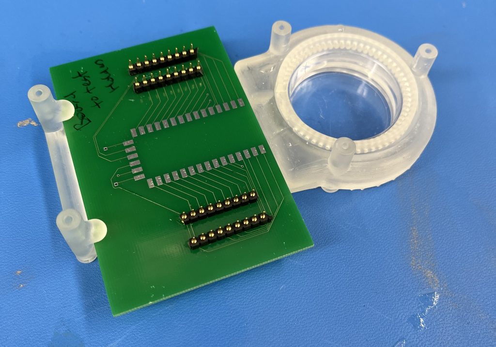
In lab, we are building a chassis/holder to insert an MEA (multi-electrode array) and a petri dish together. A thin membranous device is then placed on top to connect the MEA and cells within the petri. The goal of the device is to make sure the MEA, petri dish, and membrane do not move and break or break contact. An image of the current prototype is shown below:
However, the holder is current 3D printed for a specific size of petri dishes. This size is no longer available for use in our lab, and we now utilize petri dishes with a smaller diameter (35 mm diameter). To adjust to the size change, I will model and 3D print (Homework 2) a larger model for the petri dish.
The holder was designed with a insertable petri dish holder, which was meant to allow the user to remove the petri dish for microscopy or other assays. This is a positive design aspect, because I can use the existing chassis and just adjust the petri-dish holder.
Design Needs
The newer version of the petri-dish holder must securely hold a 35mm petri dish, and fit into existing chassis.
The design must allow for airflow between the environment and the interior of the petri dish for gas exchange.
The design must allow for the petri dish top to be placed on top.
Drafting and Measurements
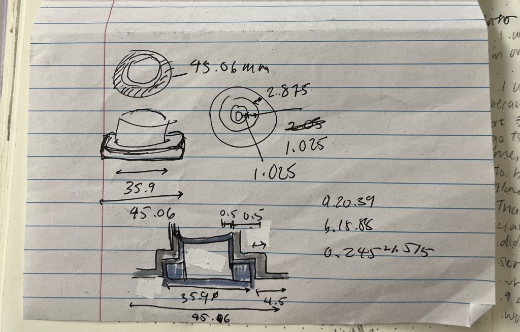
To start, I measured the multiple diameters of the larger petri dish and the smaller petri dish, the current petri dish holder, and the MEA chassis. Shown below are the initial sketches, measurements and existing dimensions.
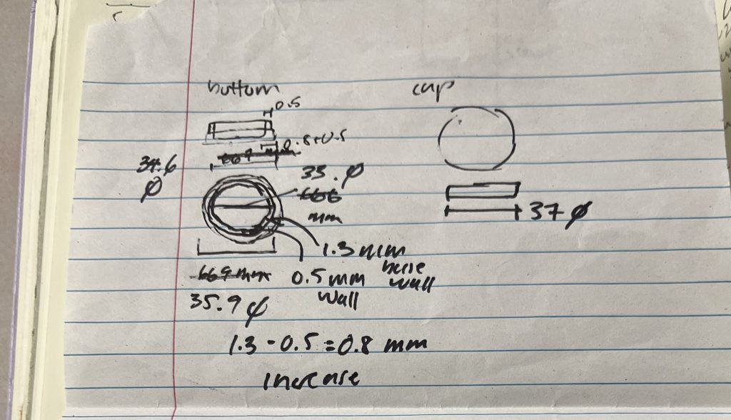
35mm petri dishes have a profile akin to a two-tiered cake. The bottom half of the petri dish juts out with a greater diameter, rather than being a straight wall. I measured the thinner upper walls and the thicker lower walls of the petri dish. I also measured the height of the thinner and thicker portions, and the total height of the dish.
I measured the existing design diameter, the diameter of the chassis insert hole, and the change in diameter between the larger and smaller dishes.
Initial Design
Luckily, the design and needs to be addressed were already accommodated in the larger design. So, the major aspect I needed to address was the change in diameter. My solution was to add a ‘skirt’ at the circumference of the design to fit into the existing hole.
SolidWorks Process
The design was made in SolidWorks using mmgs (millimeter, gram, second)and ANSI measurement settings.
Step 1: Basic Shape Outlines
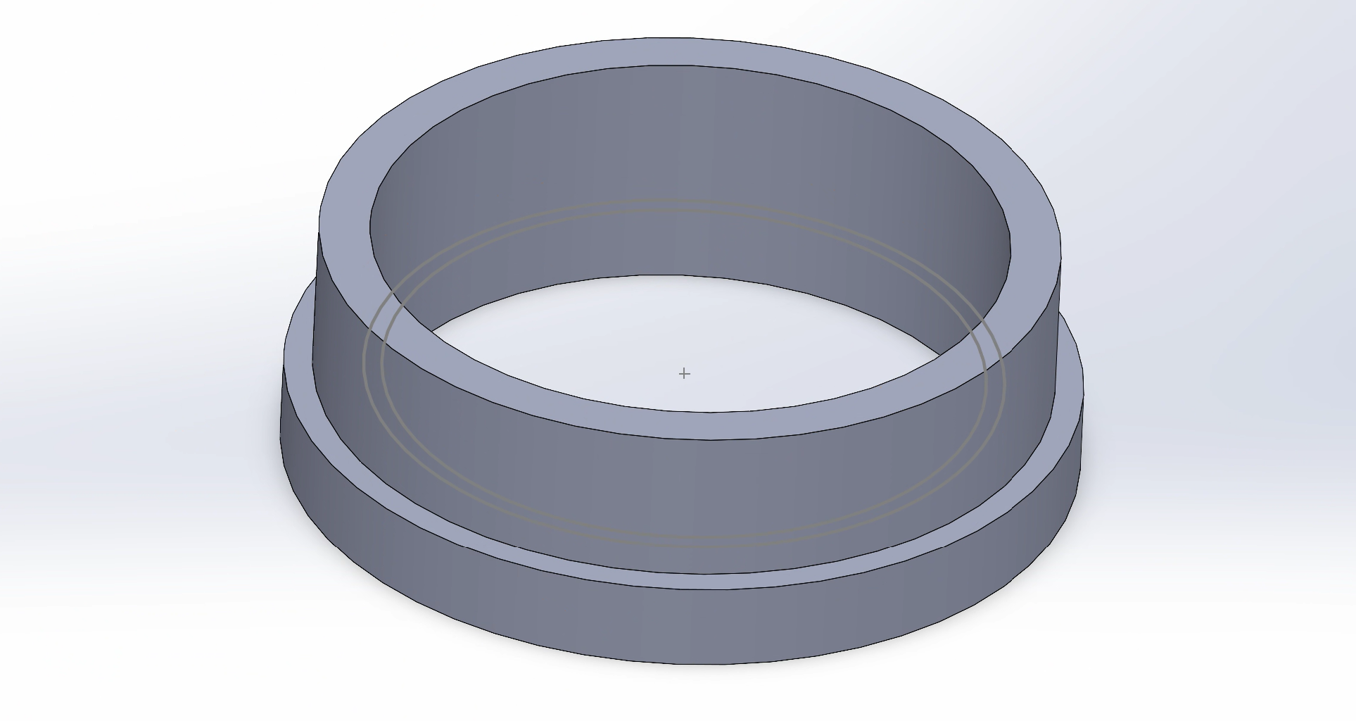
I started the holder with two extrudes of circles. The most outer walls are meant to close the gap between the petri dish and chassis hole. The innermost diameter is meant to fit around the outside thick wall of the petri dish (~37mm diameter). Note that the inside is smooth, and the inside wall does not change in diameter. This will be a crucial difference in the next step.
Step 2: 3-Tiered Interior
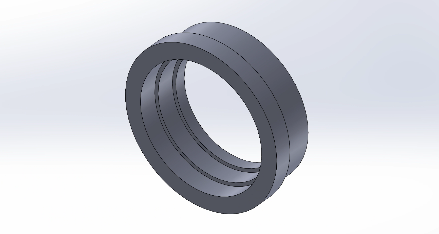
Next, I added a third ‘tier’ or layer onto the holder using extrude functions. Notably, this next step does not change the total height of the design. Furthermore, this step adds three layers into the inside of the design; however, the outside of the design is still two layers. The top-most layer will be changed in the following steps.
Step 3: Upper Lip Groove
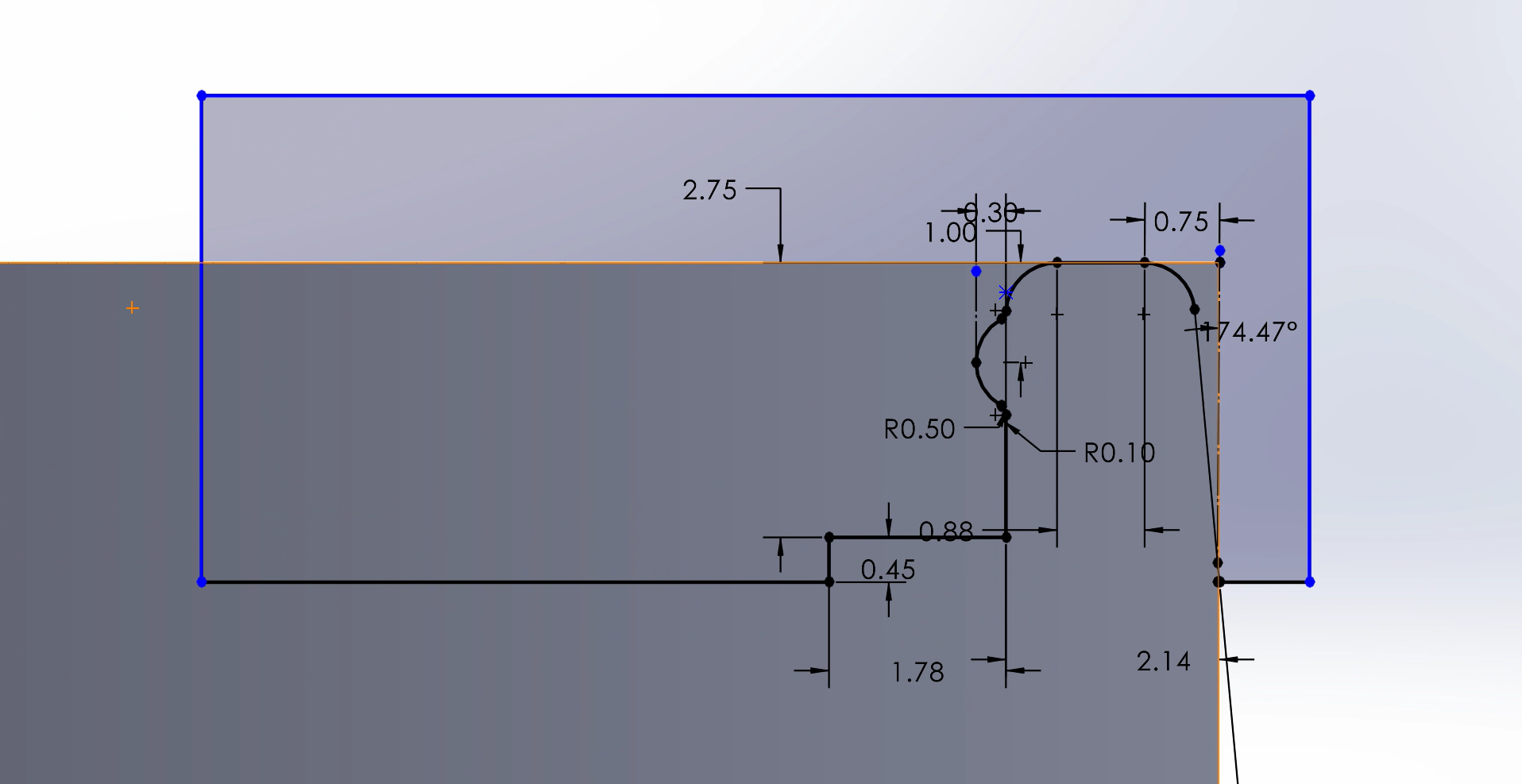
Next, I added a lip to the uppermost lip of the holder using a revolved cut. This lip makes the holder’s top less sharp, and more usable in lab. Note that this design is based on the previous and larger design, but that the design and sketch do not change with the holder size. However, I wanted the current and previous design to be consistent, so implementing the new design to other lab members would be seamless. The SolidWorks sketch is imaged below:
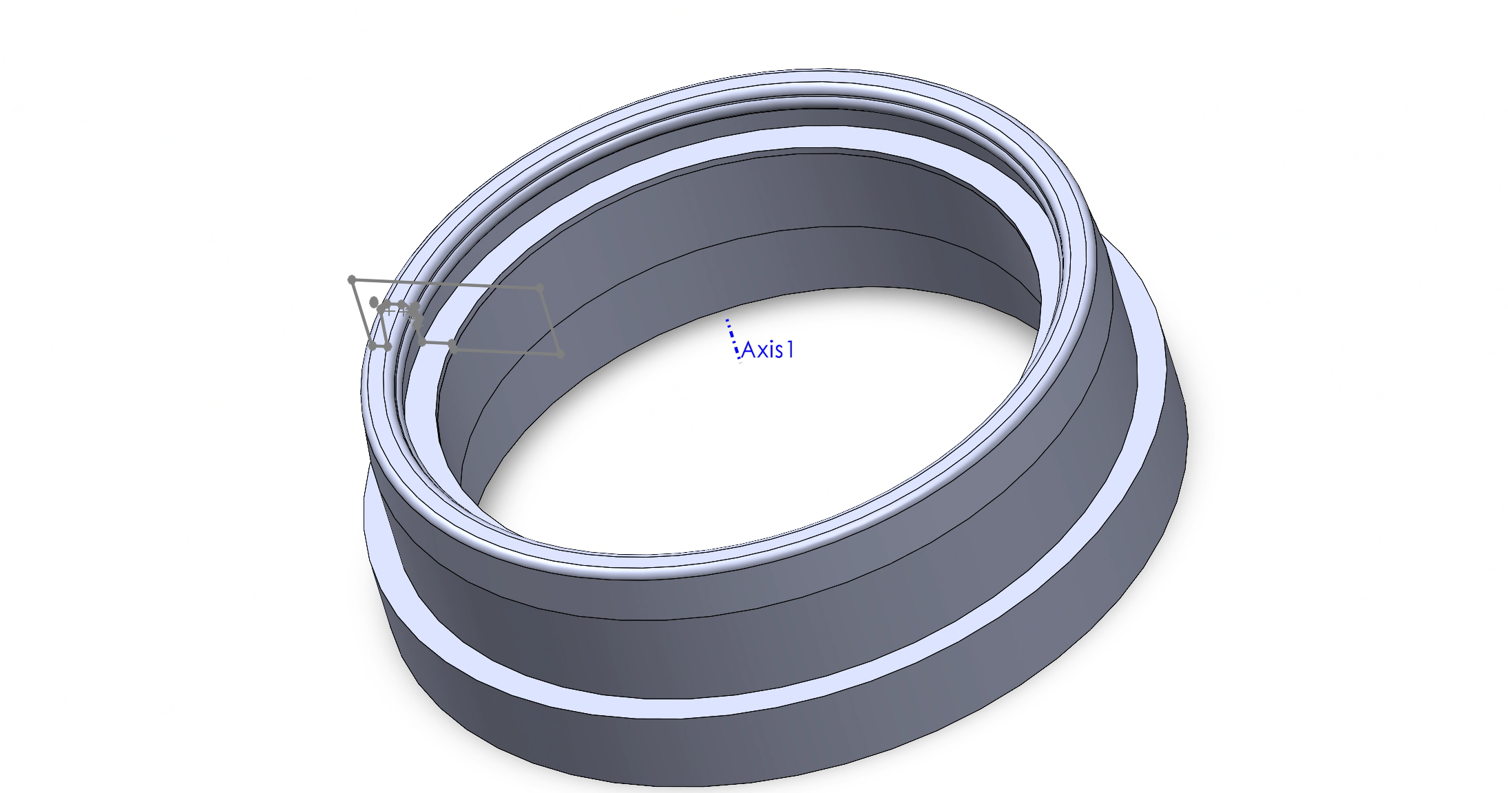
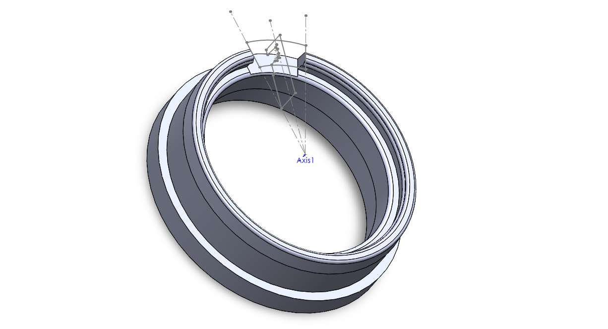
Then, I used a cut and revolve feature to apply this sketch to the entire circumference of the holder. I wanted to used a revolving sketch because this feature allowed me to add a detailed cross sectional profile of the lip. I revolved the sketch around Axis 1, as seen in the image below.
Step 4: Membrane Ramp Cut Out
Next, I needed to make a cut-out for the membrane to rest in as it connects between the MEA and interior of the petri dish. This feature is crucial because the device is delicate, and sudden up and down turns would increase the risk of ripping the membrane. For example, without the ramp cut-out, the membrane would have to rest on top of the lip made in Step 3, then turn sharply to rest in the petri dish.
To do so, I sketched a rounded-trapezoidal shape that would cut out a 30 degree ‘slice’ of the lip. I wanted the ramp to slope downwards as discussed above and needed the start of the ramp to be level with the rest of the chassis. I made a new plane that was parallel to the top of the newly-created lip. In the sketch, I made two concentric circles, that were also concentric to the rest of the holder. I kept the circle centers at the origin so I could keep this consistent. However, the radii of the two circles were arbitrary as long as they surrounded the upper lip. Then, I made lines that were 30 degrees apart, and used these to create a closed shape. Lastly, I used a extruded cut feature to create this cut-out, as pictured below.
Step 5: Ventilation Holes
The next step was to create ventilation holes for continuous gas exchange between cells and the environment. To do so, I used a cut-sweep feature such that the hole would point upwards when closer the center. Adding an angle to these hole was crucial because we could not risk unknown fluids (ethanol, water, etc.) from easily entering the dish. Also, the holes were cut just under the Step 3 lip.
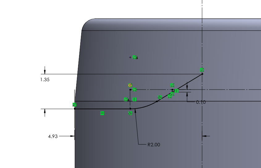
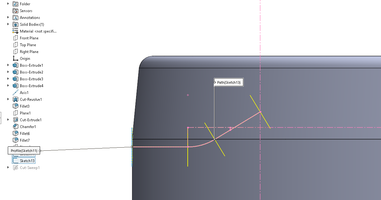
A cut-sweep feature uses two sketches: a path and profile sketch. The profile sketch is simple; a 1.50 mm diameter circle, which was 10.30 mm from the bottom surface of the holder. However, the path sketch was more complicated, as it was designed in the previous (larger) version of the holder. The path sketch consist of an arc with a radius of 2 mm, and two tangent lines. I defined the path length and tile using a total height increase and total length of the path. The sketch details can be found below.
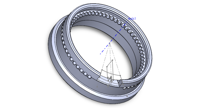
SolidWorks then automatically calculated the profile sketch along each turning point on the path sketch, as the tilted angle can be seen in below. Each short, yellow line represent the profile sketch. Each yellow line is a 1.50 mm diameter circle in the plane perpendicular to the screen, as in the plane is coming toward you vertically.
Step 6: Circular Pattern for Ventilation Holes
Next, I wanted to make a circular pattern for the ventilation holes to be repeated around the holder’s lip circumference. To do so, I used a 360 degree circular pattern to repeat the cut-sweep feature from Step 7. I then manually removed the six holes that would interrupt the ramp made in Step 4.
The image below shows most major features of this design: the extended skirt around the bottom of the holder (Step 1), the detailed lip on top (Step 3), the cut-out for our membrane device (Step 4), and the ventilation holes for gas exchange (Step 5 and 6).

However, not shown in the image are the smaller chamfers and fillets that are added to the sides of the skirt piece and bottom of the holder to smooth out the 3D printed design. Furthermore, this is not the last iteration of this design, as it must be verified and tested to fit with the new petri dishes and the existing chassis. This process will be detailed with the following assignment: Homework 2: 3D Printing.