Design and Printing Specifications
I used this assignment in conjunction with my research laboratory research. I will be printing iterations of the petri dish holder, as detailed in homework 1. To do so, I will be using the FormLabs SLA (stereolithography) 3D Printer in the Timko Lab (Sci-Tech Room 224). This setup includes a FormLabs Form 2 Printer, Wash Bath, and Curing Station, and the prints were made use the FormLab’s Clear Resin V4.
Initial Sizing Print
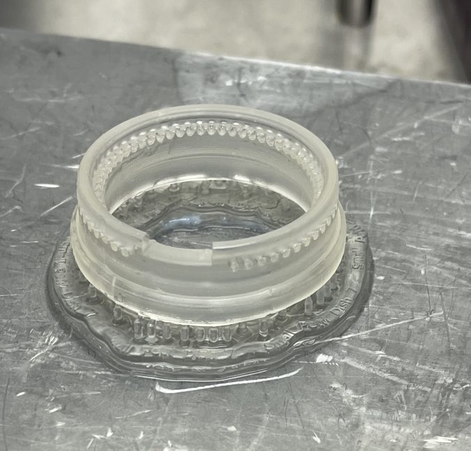
First, I wanted to print early iteration of the SolidWorks file to test the sizing of the petri dish and how it fit within the chassis, how the petri dish would inside the holder. In essence, this step was a ‘reality check,’ of sorts. While in the process of building in SolidWorks, I decided to print this simplified version:
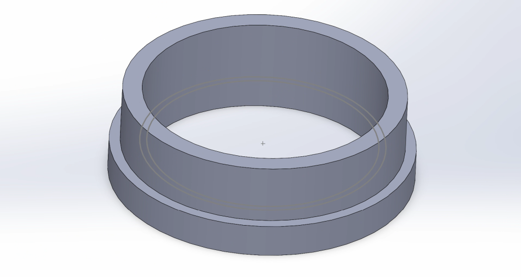
This version is from Step 1 of Homework 1.
This print took about two hours, then received a 15 minute isopropyl alcohol wash bath, then a 15 minute UV lamp curing process.
After curing the print in the UV lamp, I removed the resin print from the metal printing platform. I used ethanol to degrade the ‘raft’ supporting print, then peeled the print from the metal platform. Lastly, I cut off the thin supports from the print using pliers.
However, I made a mistake while printing this iteration and placed supports on the inside of the petri dish, which made small dents on this inside surface when I cut the supports off. This mistake made the inside of the holder bumpy and malformed, as shown below.
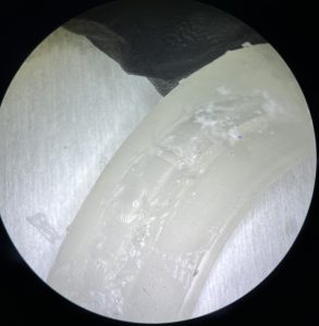
From this test print, I learned that the outer diameter of the petri dish holder was too large to fit within the chassis, and I had to adjust the final design before printing again.
Adjustments and Optimizations
From here, I needed to slightly adjust the diameter of the petri dish, as the test sizing print was a little too large to fit within the chassis.
Additionally, I wanted to optimize the resin material usage. I did so by minimizing the raft size: raft thickness and support height.
Below is a table with the change in parameters to optimize and a quantitative comparison of material usage and printing time.
| Parameters | Before Optimization | After Optimization |
|---|---|---|
| Raft Thickness | 3.00 mm | 0.75 mm |
| Support Height | 5.00 mm | 3.00 mm |
| Raft Type | Full Raft | Mini Rafts |
| Print Time | 1hr 45min | 1hr 30min |
| Resin Used | 8.17 mL | 5.94 mL |
Functional Testing Print
Then, after fixing the SolidWorks design and being mindful of placing support pillars, I had printed the final design of the holder. This corresponds with Step 6 in Homework 1.
Again, I used the same printing, washing, then curing steps. I also used a similar removal process as I have detailed above (add ethanol and let rest before removing from the metal platform, remove supporting pillars.
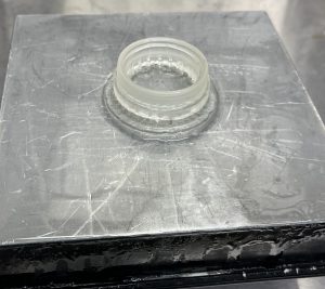
Before removal, the print looked as such:
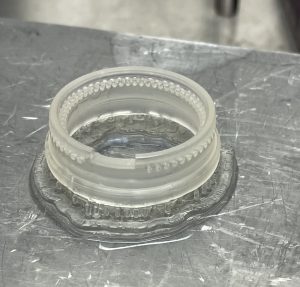
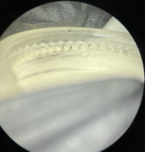
Note that in this print, all supporting pillars are in contact with the bottom surface of the print, in order to avoid the mistakes I made in the testing print. Then, I inspected the print for any major misprints, focusing on the ventilation holes.
Difficulties and Reflections
The most difficult part of 3D printing this holder was to adjust and predict any minute variations in sizing due to errors. Because this print needed very small and precise layers, it was difficult to gauge if the print had any errors until after it was processed (washed and cured). Furthermore, unlike with filament printing, the printed design with SLA printers like FormLab printers require extensive post-printing process that extends printing time.
However, the petri-dish holders (and corresponding chassis) require 3D printing to fabricate, because they cannot be made in-house in any other method. Additionally, the resin for the prints withstand the high temperature and pressure used in autoclaving, thus are viable to be sterilized and used for cell cultures.
Conclusions and Future Directions
Note that while the Functional Testing Print corresponds with the final step as described in Homework 1, it is unlikely that this is the final iteration of the petri dish SolidWorks design or the final print. The design is an iterative process, and there are many design features I have not addressed or have missed. For example, by shrinking the diameter of the upper walls to fit a 35 mm diameter petri dish, there leaves a gap between the chassis and holder. The two are no longer flush, which may be detrimental to the membranous electronic device we are aiming to protect.