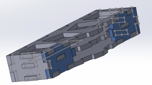
I created a 3D fidget toy based on mechanical keyboards. I wanted to challenge myself with a slanted (non-90 degree joint) design.
Table of Contents
Click on each title to navigate.
- Motivations
- Design Sketches
- CAD Work and Digitalization of Initial Sketch
- Initial Sketch into Three Dimensional Parts
- Laser Cutting
- Reflections
- CAD Files for Use
Motivations
For this homework assignment, I wanted to make a fidget toy (perhaps translatable into a keychain) of an mini-Alice layout mechanical keyboard.
As background information, mechanical keyboards use mechanical switches, which include a spring, top and bottom housing, stem, and metal leaf. For further detail on switch anatomy, click here. Importantly, switch anatomy and sizing is standardized across manufacturing companies, so they can fit into any hole that is the correct size. However, people can be very particular regarding the details of a switch and it’s impact on the keyboard’s sound and feel.
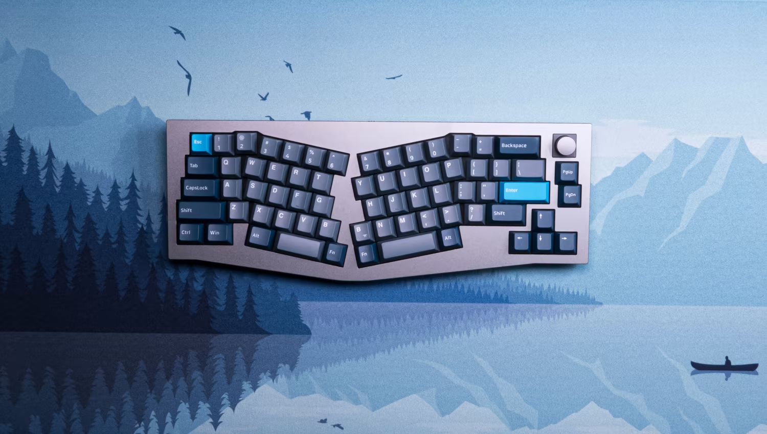
An Alice layout keyboard is slightly slanted toward the middle and is meant to promote more ergonomic wrist positions while typing. If you place your hands comfortably on a keyboard, you might find that your index finger rests on a row below your middle and ring fingers, with your thumbs positioned below on the space bar. In other words, your fingertips may not rest all on the same row of the keyboard, to which an Alice layout keyboard is meant to address. A typical Alice layout is shown below, with variations in escape keys, inclusion of arrow keys, knobs, etc.
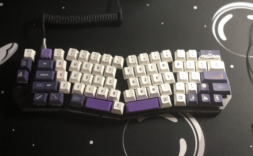
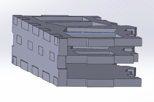
In total, I wanted to make a small fidget toy with four mechanical switches in the shape that represents an Alice keyboard layout (because it’s my favorite). My current keyboard is shown below:
Design Sketches
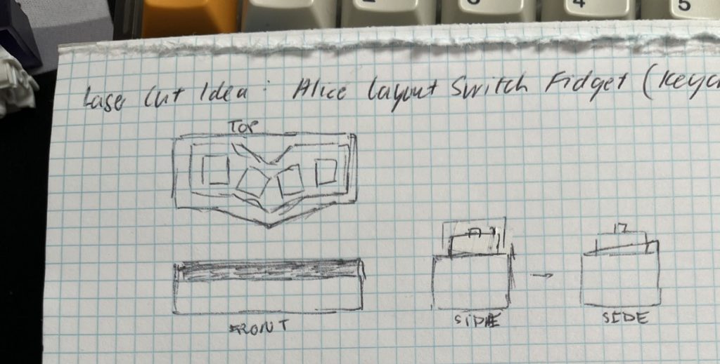
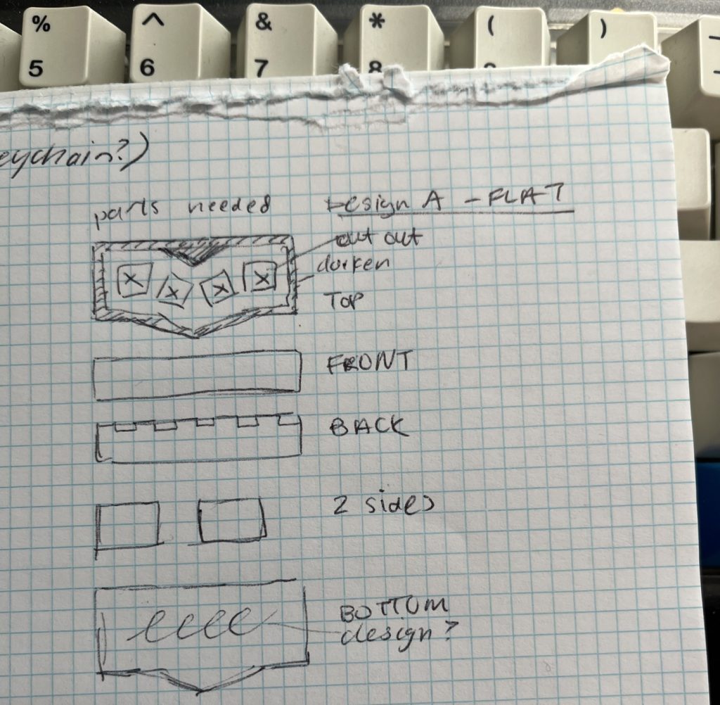
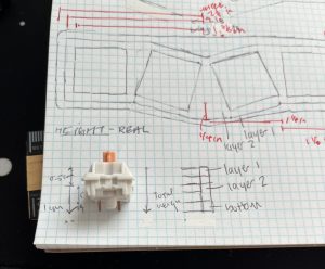
To start, I sketched a loose Top, Front, and Side views of my fidget toy, noting the slanted middle of the design.
Then, I sketched two possible designs: the first where the top of the toy was flat, and another which was slanted. These sketches included Top, Front, Back, Sides, and Bottom designs.
Design A – Flat
Design B – Slanted
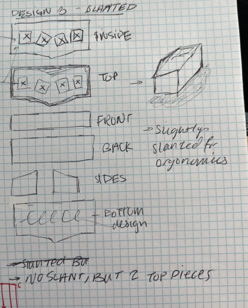
I ultimately chose the flat top to simplify the CAD work and laser cutting processes. Mainly, by keeping the top of the toy flat, the finger joints between the top and connecting pieces would be at 90 degrees. If I had chosen a slanted design, these joints would not be right angles, which would make the cutting and assembly of the parts more difficult.
Then, I watched a video on laser cutting then fabricating boxes. I then added a small sketch of a finger-jointed box for future referencing:
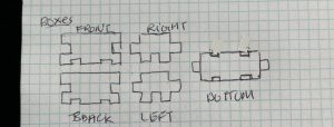
Notably, this sketch does not include the inside-tier plate, of which I designed for in the CAD process.
Next, I created a more refined layout with one-to-one ratio dimensions (the dimensions of the final toy would be the same as the drawing). I did so by tracing the outline of keycaps in the locations and slants that I wanted. The first version of this sketch (top) was too far spaced in the middle. This problem was solved in the second sketch (bottom), with less space in the middle. Using this sketch, I measured approximate dimensions of the final toy. To note, the design is symmetrical, and lines appearing to be center lines should be assumed to be centered.
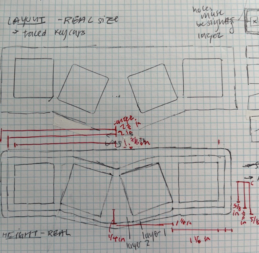
Lastly, I wanted to layout the real height a mechanical switch, and begin ideation on the thickness of layers and the distance between them. I needed these dimensions to be correct in order to fit the switch into the toy.
With a more refined sketch in hand, I then transferred this design into AutoCAD.
Common Dimension Conversions
Below are some common dimension conversions between imperial and metric units for your convenience.
| Imperial | Metric |
|---|---|
| 0.39 inches | 1 cm |
| 0.20 inches | 0.5 cm |
| 0.118-0.12 inches | 3 mm |
CAD Work and Digitalization of Initial Sketch
I had first sketched this design into AutoCAD. Throughout this process, I checked the dimensions I had measured with standardized measurements of the keycap and switches.
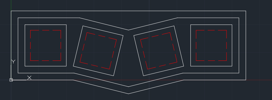
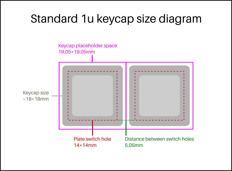
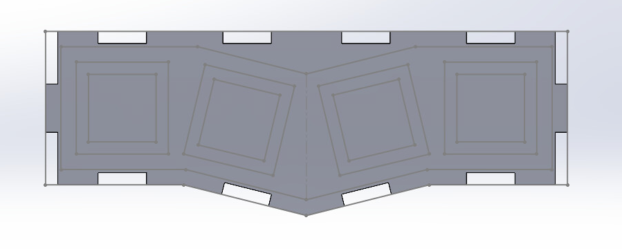
Generally, parallel white lines were made by an offset of 3mm (0.118 inches). In the dashed red lines were holes made to fit the mechanical switch. The white boxes directly surrounding the dashed white lines were made to fit the keycaps. The red dashed boxes were ~14×14 mm, while the white keycap holes were ~19x19mm. These two would be made into two different layers.
Initial Sketch into Three Dimensional Parts
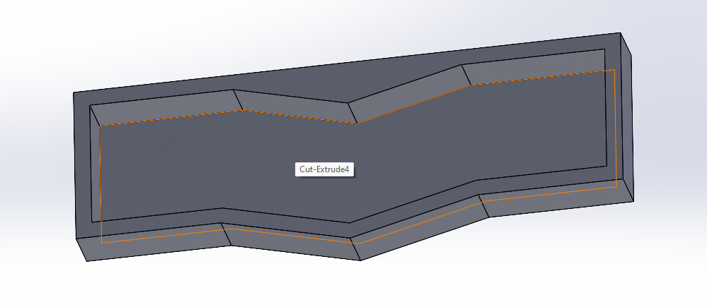
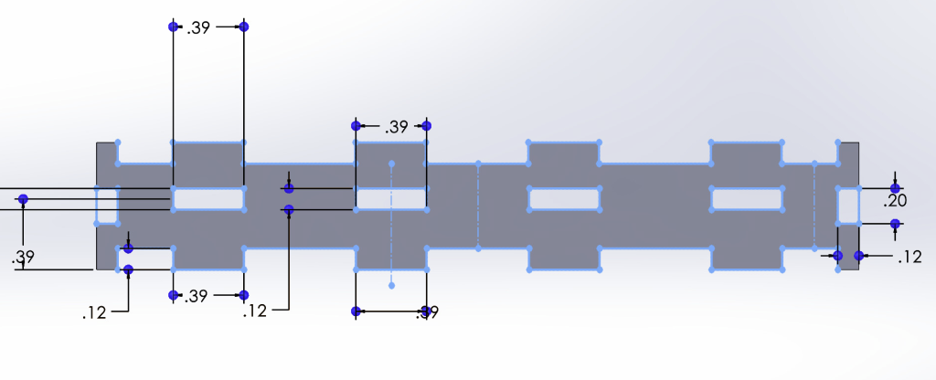
At this point, I realized I had made a mistake by starting the initial CAD in AutoCAD, rather than SolidWorks. I then had to transfer the AutoCAD 2D drawing into SolidWorks as a sketch. Then, I gave the sketch height using an extrusion, then cut out the middle to resemble a typical Alice keyboard case. Note that for this project, the displayed dimensions are in inches.
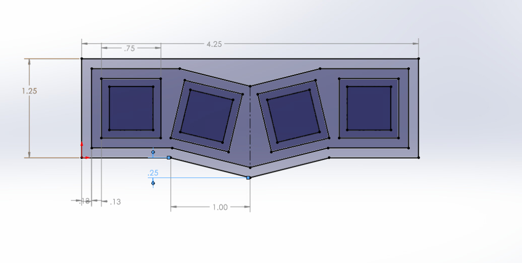
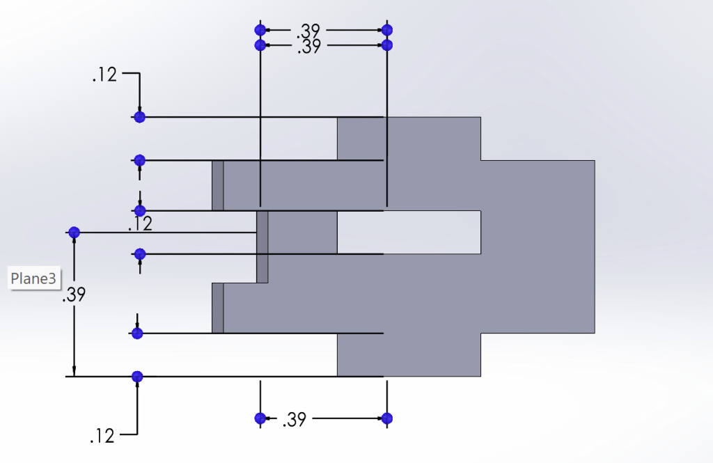
Displayed below are the total width and length, width of boxes, offsets between parallel lines, and the dimensions of the tilted middle. Notably, one thing I had missed was the degree angle of this tilt.
I then extruded this into a case-like part with a height of 1.5cm, as determined by the height of a switch (~1cm). Later, I added another 3mm in the opposite direction of the original extrude to create finger joints that accommodated the added height of the top plate.
This three-dimensional extrusion would be helpful moving forward, as I wouldn’t need to redefine the dimensions of the back, side, and front panels.
Top, Bottom, and Inside Plates
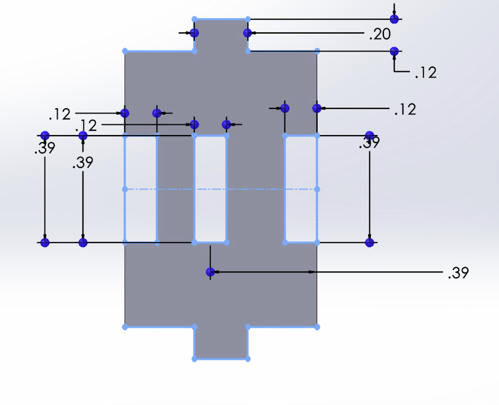
I first started with the Top, Bottom, and Inside Plates of the design because they were all similar in shape and would help me to visualize the rest of the design. For these three, I had chosen the inlet vs. outlets of the finger joints based on the research I had done earlier. Throughout the design, I had used finger joint rectangular holes that were 1cm in length and 3mm in width to fit the 3mm birch wood I was planning to laser cut from. If not specified, assume these dimensions for finger joints.
Shown above is the bottom plate, which has no holes cut out but has inlet finger joints on the north and south sides, then outlets on the west and east side.
Above the bottom plate would be the inside, mechanical switch plate with ~14×14 mm holes. To make this, I had copied the bottom plate and cut out the inner square holes.
Above the middle layer plate would be the keycap or top plate with ~19×19 mm holes. Similar to the two above plates, I had copied the bottom plate and cut out the outer square holes.
Lastly, I extruded of the sketches to a height of 3mm, or the real thickness of the birch panels.
Back Panel
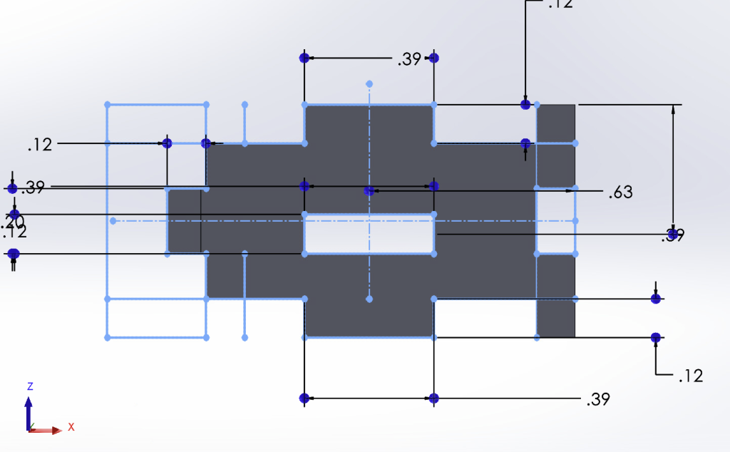
I then designed the finger joints of the back panel, now knowing the placements of the bottom, middle, and top layer plates. Note, the back panel refers to that which is not tilted / in the v-shape.
Notably, there is a finger joint hole in the middle of the back panel to fit the middle layer. This joint hole is centered to 1cm above the bottom edge of the back panel. This is based on information regarding the height of mechanical switches.
From this point on, I began adding the back panel with the bottom, middle, and top plates into a SolidWorks Assembly file. I did this to ensure that the real cuts would fit into the finger joints and holes after laser cutting. Pictured below are the top, middle and bottom plates mated to the back panel.
At this point, I was relieved because the middle-layer holes in the back panel had fit the 3mm thick middle plate.
Side Panels
The side panels were designed in a similar way, with the same middle layer finger joint hole 1cm [0.39 inches] above the bottom edge. For the side panels, I didn’t need to make different designs for the left and right panels, as they were mirrored and symmetrical. Notably, for the side finger joints (those pictured on the top and bottom of the below sketch, in blue), I used a width of 0.5cm. This is because a full 1cm width would take the majority of the total length.
Again, I then inserted two of the side panels into the same Assembly file, and fit them into the finger joints.
Front Panels
Of the finger joints designs I had to make, the front panels were the most difficult. This is due to two main reasons: (1) Because they were the last panels that I designed, they had to fit around the previously built parts and (2) the slanted v-shape of the front post problems in create non-90 degree angle finger joints. To overcome this, I decided to leave the tip of the ‘V’ front shape smooth without finger joints and simply glue them after laser cutting.
Most of this process was checking the existing finger joints of other parts, and fitting the front panels.
I started with the two-non slanted front panels, which almost had a ‘fish’ shape:
The above images show that the east and west sides were cut-out inlets, the north and south sides were outlets. This panel also included a middle-layer hole. After creating the right side front panel, I mirrored the design to be the left side front panel.
Again, I inserted the front panel and its mirror design into the Assembly file, mating them to the correct position.
I had the most difficulty with the slanted front panels. I was mainly confused on how I was going to connect them to the previous parallel front panels and to one another. Like previously, I was planning to create one side of the slanted front then mirror it to have the other side. (In total, the front part of the box included four panels to cut).
After much fiddling, I decided on the above design. The slanted front panels would be smooth (no finger joints) at the tip of the ‘V’ shape but include finger joints on all other sides. For this, there were outlets on the north and south sides, and a middle-layer hole consistent with all other parts (back, sides, front). Additionally, there were outlets on the sides facing the other two front pieces.
Lastly, I inserted the front panel and its mirror design into the Assembly file, mating them to the correct position. I fit the slanted front panels into the file as well, ensuring that all of the finger joints and holes were well-aligned.
Laser Cutting
Saving as a .DXF Vector File and Uploading
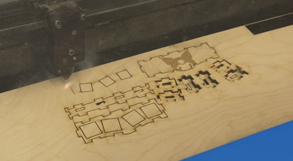
I saved all of the individual parts from the SolidWorks parts files as .DXF files. I had to select the faces that I wanted create a vector out of.
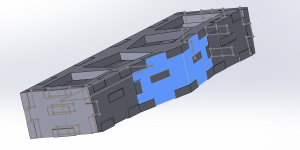
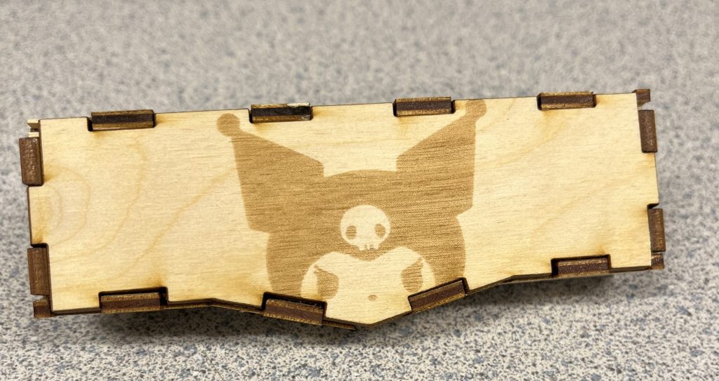
I then uploaded all of the individual parts, total 10 panels, into the Adobe Illustrator. Furthermore, I took an image from online of Kuromi, a cartoon character. I took this image, vectorized it and isolated the part that I wanted to raster on the back of my fidget toy. Through this process, I learned the basics around Adobe Illustrator, grouping/ungrouping lines, erasing lines, etc.
Laser Cutting Procedure
To laser cut, I used the Nolop FAST Facility at Tufts University. I then used the set 3mm birch wood settings at 100% intensity, 15% speed, and 3.00mm width. The Nolop laser cutters are the Universal VLS 3.60 models.
However, I had a lot of difficulty using the purple laser cutter, as the laser cutter would create very thick lines and not cut through the board. (There was a point where I had tested this laser cut five times on the same birch wood plank.) Then, I tried the same on the blue laser cutter, which worked much better, had thinner cutting lines, and cut all the way through.
I adjusted the previous Adobe Illustrator file into the laser cutting software to take up as little space as possible, mindful of the resources I was using. I then added the Kuromi vector image onto the back panel of the toy in grayscale.
For the full video of the laser cutting process (~4 minutes), please see the Box Drive at the bottom of the page.
Physical Assembly
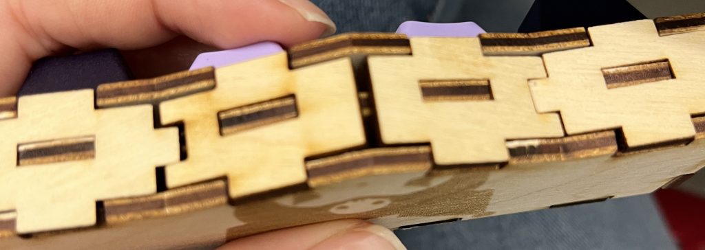
Throughout this process, I recruited the help of a mechanical engineering friend (shoutout Hudson), who said that it was ‘fun’ and ‘like legos’. We started the assembly by attaching the top, middle, and bottom plates to the back panel. Then, we attached the two side pieces, then the front parallel pieces, then the front slanted pieces.
There were some finger joints that had cutting malformations that did not fit together perfectly. To adjust to this, we sanded down joints that were extruded too far. Then, for panels that were wiggly, we used super glue to firmly attach the joints. Mainly, we used the glue on the front two slanted panels.
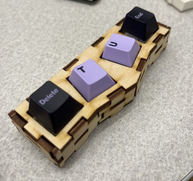
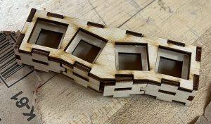
Then, I inserted four Drop Holy Panda V2 mechanical switches into the holes. These fit perfectly, snapping into place firmly. Out of the four, only one square hole had been larger. This mis-cut wasn’t in danger of falling out, but we needed less force to pull it out.
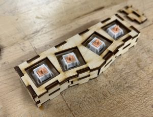
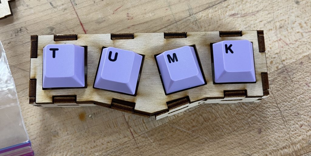
Lastly, I added four keycaps (T,U,M,K), which stands for Tufts University Mechanical Keyboards- one of the clubs I am in!
Reflections
In total, I was pleasantly surprised about this assignment. While using the laser cutting program was frustrating at first, the cutting time was fairly quick and only caught on fire once.
I were to restart the project with my current knowledge, I think I would adjust the ‘order of operations’ that I did the SolidWorks in. I did the most difficult finger joints last, meaning I also had to maneuver around both constraints (surrounding finger joints and slanted angle).
I think that laser cutting is particularly useful for more precise woodworking tasks, compared to handsaw or other tools that are less precise. Furthermore, the laser cutting has a smaller scale and can cut more precise and clear 90 degree corners. However, laser cutting has faults in that there may be slight tolerance issues due to the laser cone shape. Additionally, finger joints and laser cut and assembled parts feel more loose and at-risk of falling of/out. In total, while laser cutting is preferable when fabricating smaller scale objects, traditional woodworking methods are preferable when working on a larger scale and are more stable.
In the future, I would raster around the visible finger joints to create a more cohesive aesthetic. Also, I realized I was missing a raster detail on the top plate.
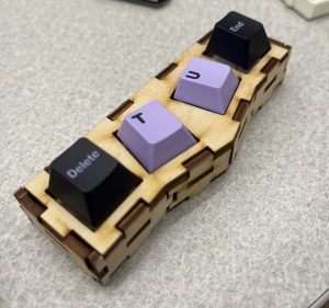
Lastly, during the process of assembling the toy, we had broken some of the more delicate corner joints, pictured below. Also, I made some mistakes while doing the CAD for the front slanted panels, as there were large gaps between the finger joints.
I would have to adjust the length of the front panels to make sure that this hole doesn’t recur in future laser cutting.
CAD Files for Use
If you wish to explore/modify/laser cut a fidget toy yourself, please visit this Box Drive that includes all of the .DXF and .AI files to laser cut.