Table of Contents:
- Ideation and Design
- Physical Wiring and Breadboard
- Coding Process
- Reflections
- Citations and Datasheets
- Provided Code
Ideation and Design:
I wanted to utilize my work from the previous assignment by soldering mechanical switch pins to wires, then attaching those wires to the microcontroller. Essentially, I wanted to make my mini fidget keyboard functional. However, I avoided this idea because I didn’t want to permanently solder wires. Also, I realized through in-class work that many of the sensors (humidity and temperature, ultrasonic distance) were finickity, and often wouldn’t report the correct output.
To design around this, I used the buttons provided with the microcontroller kit to replace the keys. Using the buttons I wanted to design a morse code decoder to type out messages. I thought the button / press sensors would be best to use because they are very intuitive to use, and there were multiple within the kit. Lastly, the buttons were the most similar to keys on a keyboard.
Physical Wiring and Breadboard:
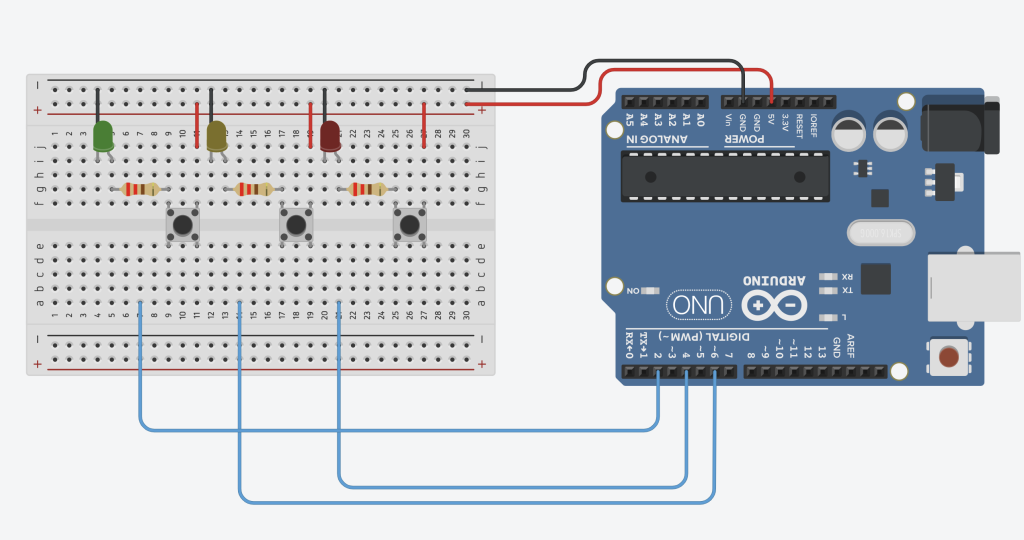
As shown above, each button ‘module’ includes the button itself, a connection to the digital inputs of the Arduino, a 220 Ohm resistor to a colored LED, and then connect back to the positive and negative rails.
When built physically, the Breadboard looks like this:
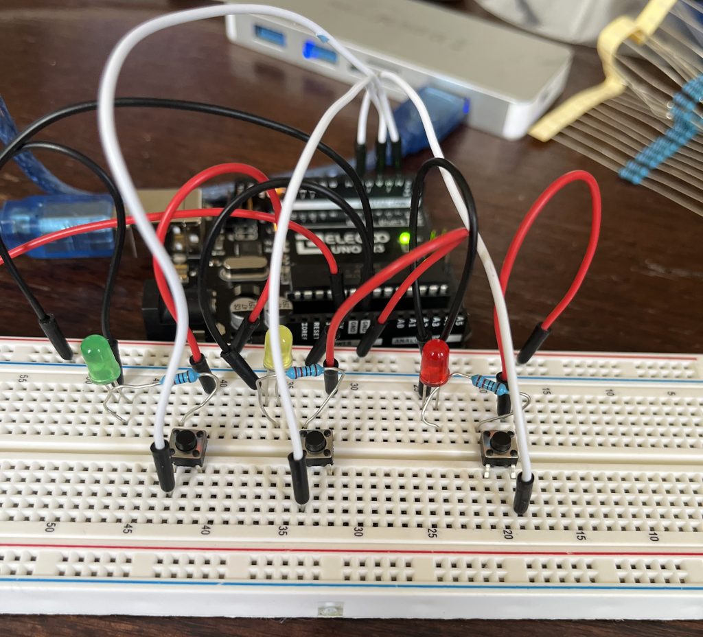
I chose to include the LEDs to help label what each button does to increase the accessibility of the device. Also, this helps to show when the button is pressed to have visual confirmation that of the button’s state. This is done solely through the wiring, as pressing down the button completes the circuit and allows charge to flow through the LEDs. In other words, there is no communication between the LEDs and Arduino microcontroller.
Coding Process:
I decided to write the code for the main input button first. From there, the same coding structure was copied for the other two buttons, just adding different functions within the if statements. Below are some snippets of the code I developed that are relevant to explain the overall flow of the code, without providing every detail. If you are interested in the full code, please see the Box Drive for the available final code.
Coding Initial Variables
 const int buttonPin1 = 2; // Button Number 1 Input
  int button1State = 0;     // Button Status (0/1)
  int button1Press = 0;     // Time of button press
  int button1Release = 0;   // Time of button release
  int button1Duration = 0;  // Time between press and release
  int button1PreviousState = 0; // Placeholder to avoid unwanted presses
  int CurrentTime = 0;      // Used to count internal time, time since code started


---

int Letter[5];           // integer array to hold dots and dashes
  int CurrentLoop = 0;     // loops through dots and dashes in Letter when translating
  String CurrentWord;      // Output String

// Morse Code Arrays
  char* AlphaNumericals[36] = {"A","B","C","D","E","F","G","H","I","J","K","L","M","N","O","P","Q","R","S","T","U","V","W","X","Y","Z","1","2","3","4","5","6","7","8","9","0"};
  int MorseCodes[36] = {12000,21110,21210,21100,10000,11210,22100,11110,11000,
12220,21200,12110,22000,21000,22200,12210,22120,12100,11100,20000,11200,
11120,12200,21120,21220,22110,12222,11222,11122,11112,11111,21111,22111,
22211,22221,22222};
The section above the dividing dashed lines is from the Button 1 variable setup. Please note that the “buttonPin,” “buttonState,” “buttonPress,” “buttonRelease,” “buttonDuration,” and “buttonPreviousState” are then copied as variables for Buttons 2 and 3. The only difference is the number within each variable name.
Then the Letter[5] integer array holds the sequence of dots and dashes for a single letter, the CurrentLoop is to count which index within the Letter[5] array is currently changing, and the CurrentWord is the string that is printed to the Serial Monitor.
Finally, the morse code arrays are two arrays (AlphaNumericals being a character array and MorseCodes being an integer array). Note that these arrays are used to translate the inputs codes from the user into letters and numbers. Each sequence of 5 numbers within MorseCodes translates to the corresponding index of AlphaNumericals. The matching indexes are later used to translate and generate the correct letter or number.
Setup Void Function
Establishes the pinModes and inputs of all three buttons, and beings the Serial Monitor. Furthermore, the initial instructions on how to use the program are output here. Below are the instructions, not the code for the instructions, for usage:
Morse Code Instructions
-----------------
Use the Left Green Button to input your morse code, a press of less than 0.5 sec is a dot (.),
and a press of more than 0.5 sec is a dash (-)

Wait until the letter has been printed before inputting the next letter.

Press the Middle Yellow Button for 0.5 sec to add a Space.

The Right Red Button is for Backspace and Delete. Press it more than 0.5 sec to backspace,
and more than 2 sec to delete the message

Happy Morse Coding!
If you need the instructions again, press the Middle Yellow Button for 1 sec.
The abbreviated instructions are as follows:
Abbreviated Instructions              // Print out instructions--------------------
Left Green Button:
< 0.5 sec = dot '.'
"> 0.5 sec = dash '-'
Middle Yellow Button:
> 0.5 sec = space
> 1 sec = Instructions
Right Red Button:
> 0.5 sec = backspace
> 2 sec = delete entire message
--------------------
Button Timing and Press Sensing
button1State = digitalRead(buttonPin1);
if (button1State == HIGH && button1PreviousState == LOW) {
    button1Press = millis();
    button1PreviousState =
    digitalRead(buttonPin1);
 }
if (button1State == LOW && button1PreviousState == HIGH) {
    button1Release = millis();
    button1PreviousState =
    digitalRead(buttonPin1);

    int button1Duration = button1Release -
    button1Press;

    if (button1Duration > 500) {
    Serial.print("_");
    Letter[CurrentLoop] = 2;
    CurrentLoop += 1;
    }

    if (button1Duration < 500) {
    Serial.print(".");
    Letter[CurrentLoop] = 1;
    CurrentLoop += 1;
 }
Code Comments:
– Sense the downstroke – Read time of press, and set PreviousState variable
– Sense the upstroke – Read the time of release, and set PreviousState variable
– Calculate duration of press
– if press is more than 0.5 sec., enter a ‘2’ into Letter[5] array for a dash ‘_’, increase index
– if press is less than 0.5 sec, enter a ‘1’ into Letter[5] array for a dot ‘.’, increase index
Here, I wanted to create a system that would time the duration of the user’s presses. This is important to differentiate between dots and dashes. The following code details the outline structure for Button 1. However, the coding structure for Buttons 2 and 3 are similar to find the timing. However, the executables for each are different.
Generally, the structure is as follows: the program only senses the time of the downstroke if the previous state was the opposite state. This is to ensure that holding down the button only reads as one time (at the beginning of the hold). For the downstroke (when the current state is high and previous state was low), record the time and set the ‘PreviousState’ variable to the current state (high). Then, when the button is released on the upstroke, again sense the time that the button is released. Again, set the ‘PreviousState’ variable to the current state (now low). Then, define a variable that is how long the button was held down for. If the duration is greater than 0.5 sec (500 milliseconds), this is registered as a dash ‘_’, and store this in the current index CurrentLoop variable into the Letter[5] array. Alternatively, if the duration is less thant 0.5 sec, this is registered as a dot ‘.’ and again stored into the Letter[5] array. After each input (dash or dot) is saved into the Letter[5] array, add 1 to the current loop. This is to make sure that the subsequent input does not override previous inputs.
Automatic Wait Time and Morse Code Translation
Then, I created an automatic wait timing before the program translate the current Letter[5] array into a letter or number. This means that if X-seconds go by without any user input, the translation code is run. However, the user has X-seconds to add additional inputs to their current code. I did this by again using the intrinsic timing system within Arduino.
CurrentTime = millis();
  int button1Pause = CurrentTime - button1Press;
  if (button1Pause > 3000 && Letter[0] != 0) {

    int CurrentCode;
    int Let = 0;
    for (int j=0; j<5;j++) {
      Let = Let * 10 + Letter[j];
    }

    for (int i=0; i<36; i++) {
      CurrentCode = MorseCodes[i];
        if (CurrentCode == Let) {
          Serial.println("");
          CurrentWord = CurrentWord + AlphaNumericals[i];
          Serial.println(CurrentWord);
          Serial.println("");
        }
    }
    for (int i=0; i < 5; i++) {
       Letter[i]=0;
    }
The code above takes the time of the previous user’s inputs and compares it with the current time. Then, it subtracts the two to find the length of the pause, and the time since the last press. Following, if the pause time is greater than 3 seconds and the Letter[5] array is not empty, the following code is executed. The emptiness of the Letter[5] array is done by checking the first index of the array. If the first index is 0, then the user has not input any dots or dashes, and the following code is skipped. If both conditions are met, the integer Let is created. the next for loop translates the Letter[5] integer array into ‘Let’ integer. This step is crucial for the following Morse Code translation because of the ways the dots and dashes are currently stored. The Letter[5] integer array stores the integers as separate numbers, such as {1,2,3,4,5}, while the Let integer must be in {12345} to be compared to the MorseCodes array. So, a commonly-used translation method of multiplying by 10 then adding the next letter was implemented. To visualize this:
Letter[] = {1,2,3,4,5}
Let = 0;
Expanded Loop:
Let = 0 + Let[1] = 0+1 = 1
Let = 1*10 + Let[2] = 10+2 = 12
Let = 12*10 + Let[3] = 120+3 = 123
Let = 123*10 + Let[4] = 1230+4 = 1234
Let = 1234*10 + Let[5] = 12340+5 = 12345
Note that this is not code within the Arduino code file, just a visualization of what happens within the loop. Also, this is why the dash is stored as ‘2’ and dots as ‘1’, instead of as ‘1’ and ‘0’ respectively. If the dot input was ‘0,’ the empty spaces of the Letter[5] array would be empty, and the above calculation would not be possible.
Next, the program takes the new Let integer and compares it with the the Morse Code array that was defined in the variables section. Here, the program loops through 0 to 36 and checks for which integer within MorseCodes matches with the Let integer. If the two integers are equal, the correct code is found. Then, the corresponding AlphaNumerical character (A-Z, 0-9) is concatenated onto the CurrentWord String.
Finally, to reset the code and prepare for the next sequence of inputs, the Letter[5] array is reset to 0. Furthermore, the CurrentLoop variable is reset to 0, so that the program can recognize the next set of inputs.
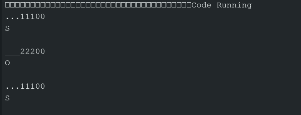
With this, I was able to type out letters!
Buttons 2 and 3 – Space and Backspace
The same button timing structure is repeated for buttons 2 and 3. Note that for these two buttons, their position is switched between the Arduino Code and Breadboard. I had first written the code for backspace, then the code for adding a space. So, button 2 within the code corresponds to the Right Red button on the Breadboard, and button 3 corresponds to the Middle Yellow button. I had made this order change because it felt most logical to have the Delete and Backspace button furthest from the input button.
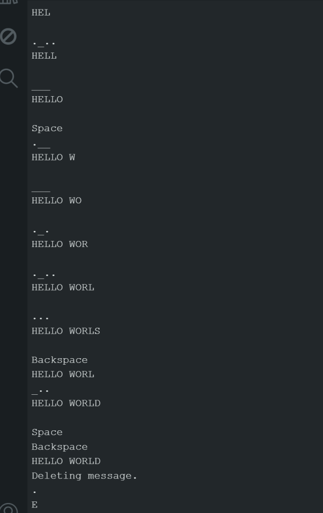
For button 2, which is the delete and backspace button, if the button press duration is greater than 2000 milliseconds (2 secs), the CurrentWord Variable is set to “”, which is an empty String. If the button press duration is greater than just 250 milliseconds (0.25 sec), then the code removes the last letter of the CurrentWord string by the following code:
 if (button2Duration > 250) {
      LastLetter = CurrentWord.length() - 1;
      CurrentWord.remove(LastLetter);
      Serial.println("Backspace");
      Serial.println(CurrentWord);
Here, the LastLetter integer is assigned to the length of CurrentWord minus 1. Then, edit the string using String.remove(Index) formatting to remove the character at the last index of the string. Finally, output the current word.
For button 3, which is the space and abbreviated instructions code, the same timing structure is used to determine the length of press of the button. When the button 3 is pressed for more than 1000 milliseconds (1 sec), a series of text is output as the abbreviated instructions. If the button is pressed for more than 250 milliseconds (0.25 sec), and empty space string is added onto the end of the CurrentWord String, and the current word is output.
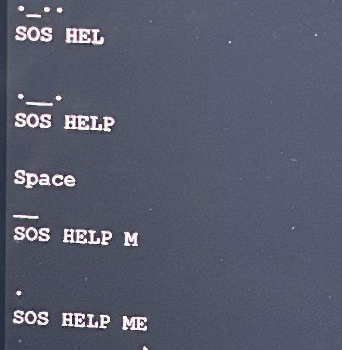
With this, I was able to write out a test with spaces and utilizing the backspace function:
Reflections:
Difficulties and Challenges
When designing this code, I had created multiple versions to track the progress and an initial pseudo code to outline the code. In past versions, I had changed the Serial Monitor output to confirm the piece of code I was currently working on. For example, when I was first designing the dots and dashes inputs, I would have the output only show the _ and . that corresponded with the inputs.
However, some errors within the code can occurs. For example, if the buttons on the Breadboard are slightly tilted or not fully placed in, this can cause more bouncing. Bouncing is when the button stem physically bounces, causing constant and unwanted inputs. There are pieces of code online to prevent the bouncing effect, but I found that slightly adjusting the metal button pins so that there was no empty space between the bottom of the button and the Breadboard prevented bouncing.
Overall, I struggled somewhat to understand the data structures within the Arduino (and C++ language). These structures were different from the ones I had previously used in MATLAB, so it was difficult to understand their usage and specifications. For example, a character is a single “A,” while a character array can be {“A” , “B” , “C”} or {“ABC” , “DEF” , “GHI”}. An integer can be “1” or “12345,” while an integer array can be {“1” , “2” , “3” , “4” , “5”} or {“123” , “456” , “789”}. Furthermore, the indexing began at 0, while MATLAB begins at 1.
When using the microcontroller, I realized that the major limitation of the board is that your designs are limited by the sensors and parts within the kit. However, you could also buy whichever parts you would want to use for a project. One major advantage would be that the board can be changed and altered easily. For example, I added the LEDs without prior plan to do so because I thought it would be a good physical indicator for when a button is pressed.
Real-World Usage
While Morse Code is not used often in the present communication, the timing structures around timing a button and comparing integer sequences could be useful. For example, this could be used to add a password onto a safe or lock in Morse Code. As a side effect, I have a fairly strong basis of Morse Code if I’m ever in an emergency situation that requires Morse Code to communicate. Not too sure if that will ever happen, but who knows what future challenges will bring. Maybe I’ll be on a survival TV show and need Morse Code.
If I had more time for this project, I would have liked to solder wires to my previous laser cutting project switches. Then, I could use my mini-keyboard as a Morse Code input.
Citations and Datasheets:
I had relied heavily on Arduino forums and online discussions to find people with the same or similar problems as myself. Through this, I found that commentors on these forums can be really sassy.
Some of my searches included:
How to convert char* to String
How to empty an array using memset
Measuring time between button presses
Convert integer array into integer
Incompatible types in assignment of ‘int’ to ‘int[8]'” error
And also this example Morse Code Project from Arduino. However, this project did the opposite of mine- by translating letter inputs to an LED flashing sequence.
I did not utilize any datasheets for this project, as I had mainly relied on forums and discussion boards. However, I’d like to point out the Arduino UNO R3 Data sheet, which is similar to the board used for this project and a very comprehensive guide on using and coding push buttons.
Provided Code:
If you would like to recreate this design, please see the Box Drive folder for the full code. Please make sure that the buttons are fully and comfortably placed into the sockets, or bouncing will occur. If bouncing does occur (a constant ‘dot’ input that won’t stop), adjust the four pin legs of the push button until the bottom of the button is flush with the breadboard.
