At first, we wanted to make a candle and candle-holder set for our 1 and 2 part molds. However, we pivoted from this idea because we were unsure if the essential oils would be delivered later. So, we decided to use materials already at Sci-Tech 252 and Nolop, but I may make some candles in the future.
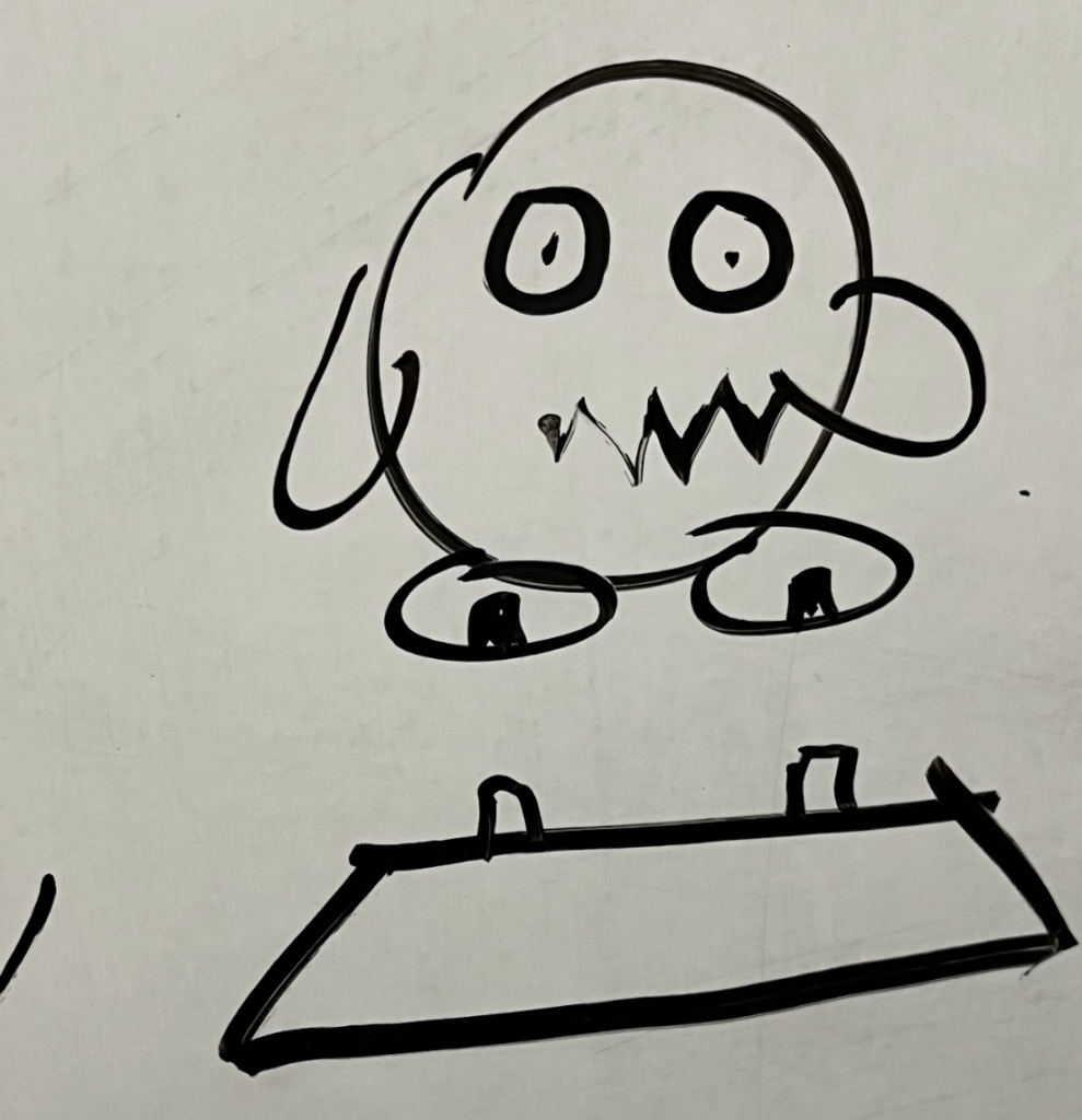
For this assignment, we decided on making a small figurine of Kirby and a base for him to sit on. The base part would have two small indents. These indents matched with the extrusions on the base of Kirby’s feet so that they would be attached. We chose a Kirby figurine because his shape is mainly round, with no sharp indents or cuts.
Initial sketch of Kirby figurine and base
1-Part Mold
Mold Material: 3D Printed
Casting Material: Smooth-Sil 940
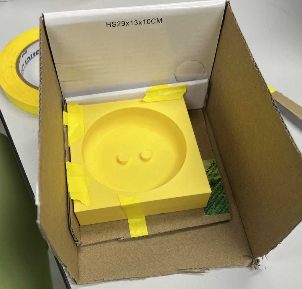
For the 1-part mold, we made a 3D printed negative of the final product. This was designed by Zahir Bashir and then 3D printed in Nolop by Maya Dubolle and Vio Ta. Then, I had done the casting using the 3D printed mold in Sci-Tech 252.
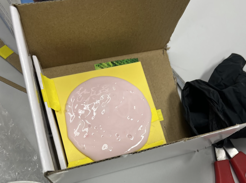
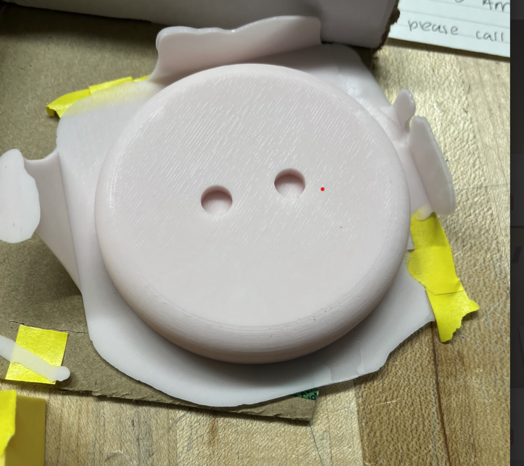
3D printed Mold for the Base 1-Part Mold3D printed Base once poured with Smooth-Sil 9403D printed Base once removed from mold
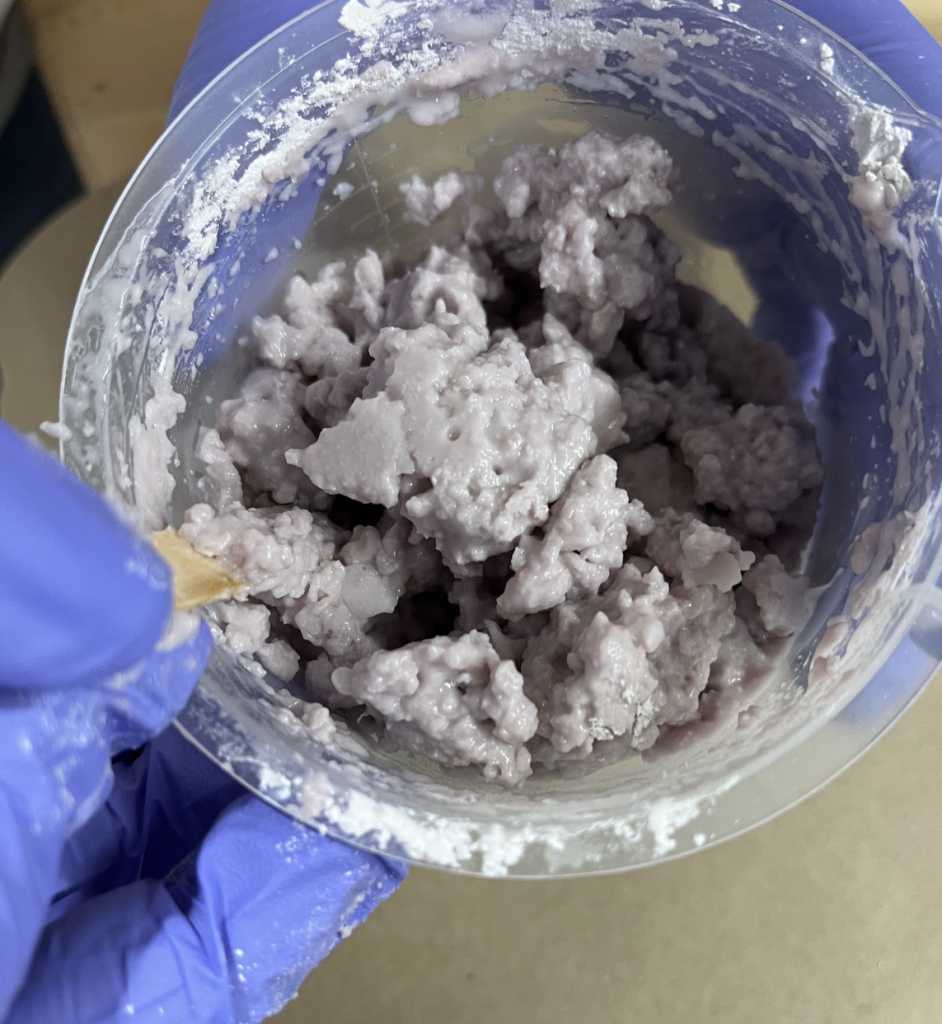
For the 1-part mold, we used Smooth-Sil 940 as the casting material. For this, I used the scale to measure out parts A and B in a ratio of 100:10 in weight. Then, I mixed and poured into the 3D printed mold to let the Smooth-Sil cure over 24 hours.
I chose this material because it was stiffer than the Mold-Max material according to the Safety Data Sheets within each box. Also, Smooth-Sil was fairly easy to remove from 3D printed plastic. Finally, I took the base part out of the 3D printed mold, and trimmed the edges that had spilt over. Furthermore, Smooth-Sil940 and Mold-Max 30 were safe to use with 3D printed material, and both materials were pink!
2-Part Mold
Object Material: 3D Printed/SLA
Mold Material: Ajla-Safe
Casting Material: Mold-Max 30
We chose the Ajla-Safe material as the molding material because of its fast cure time of about 8 minutes. Using this property, we were able to make the Alja-Safe mold and cast using Mold-Max 30 in one Nolop session, rather than having to wait 16 hours to make the top half of the mold. For this, I was at Nolop with Vio when making the bottom half of the Alja-Safe mold, but then left for class. Then, Vio and Maya made the top half of the mold and casted the Kirby. Furthermore, I was interested in using Mold Max 30 for the casting material because it was pink, and matched Kirby and our team color.
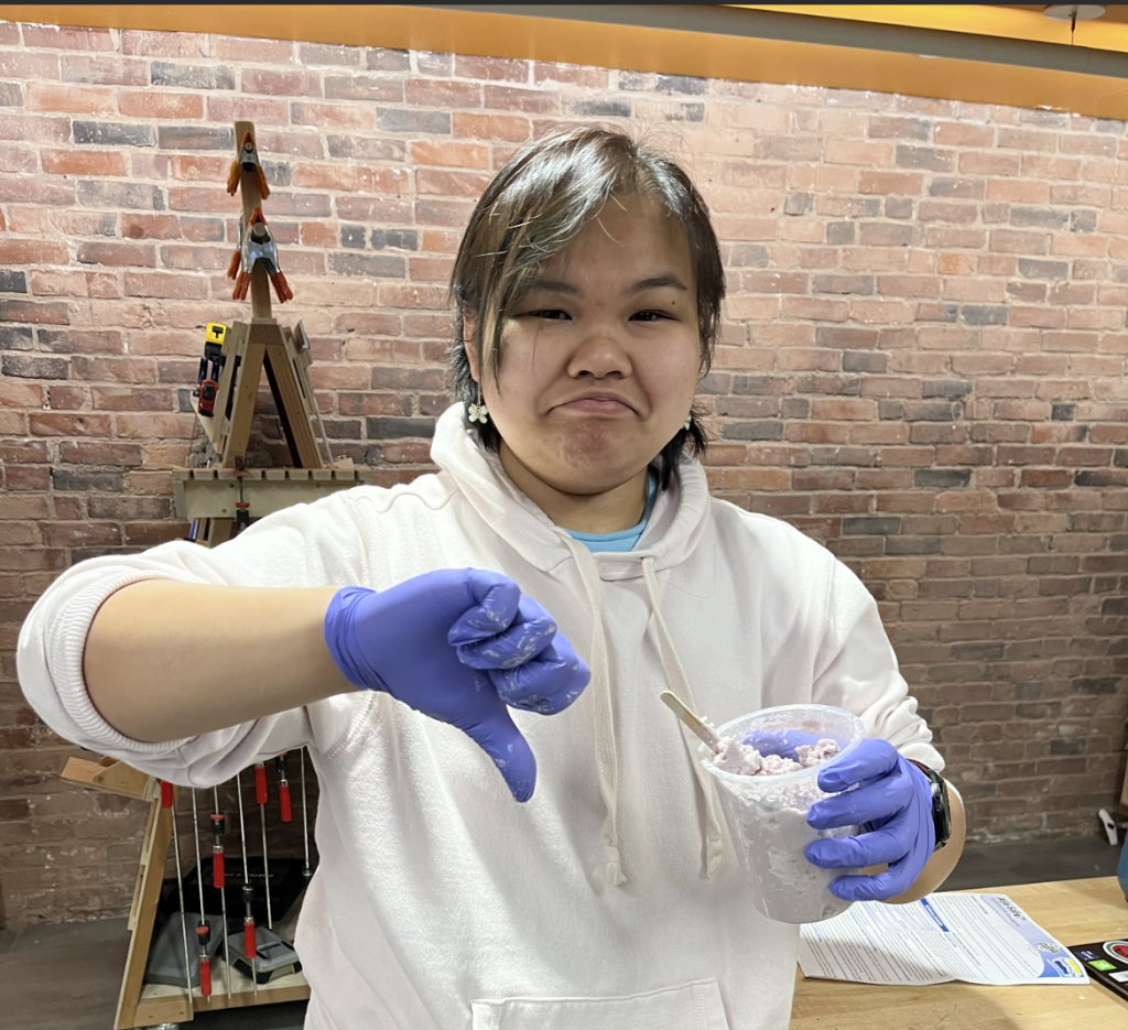
The first challenge we faced was that we used water that was too warm to make the Alja-Safe mixture. According to the Safety Data Sheet, the warmer water caused the mixture to cure too quickly, as it cured while we were still mixing (1-2 minute cure time). Then, we made another batch with cold water that did not cure as fast.
Alja-Safe mixture that was made with warm water, cured while mixingVio is very sad that the Alja-Safe cured in the pot
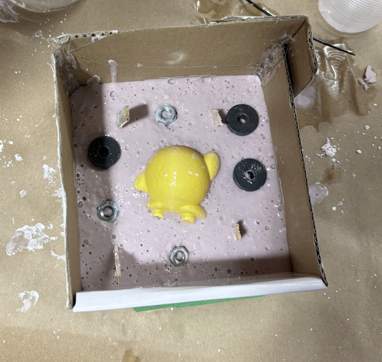
Another challenge using these materials was that we could not find clay in Nolop to set the first half of the Alja-Safe mold. Thus, we poured Alja-Safe mixture directly into the casing/box. Then, we pressed the Kirby 3D printed object into the mixture with alignment screws. However, this caused a problem because the Kirby object’s center of mass was slightly off which caused object to rotate. To solve this, Vio held the Kirby in place as the Alja-Safe cured. Furthermore, the screws were too dense compared to uncured Alja-Safe- so we placed screws in when the Alja-Safe was partially cured.
3D printed Kirby in bottom half of mold, with embedded screws
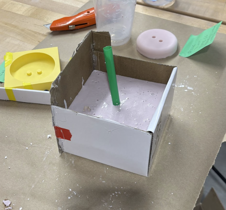
Vio and Maya found that Mold Max was less viscous, thus harder to pour into a small spout hole. This caused the final product to have bubbles throughout. So, we may want to use a thinner material in the future. Because there was no clay, they made a pouring spout using one of the green stirrers. They hot glued this to the Kirby object once the bottom half of the Alja-Safe was cured. Please see Vio Ta and Maya Dubolle’s websites for more details on pouring the mold-Max 30 material.
Green stirrer acting as the pouring spout and top half of Alja-Safe mold.
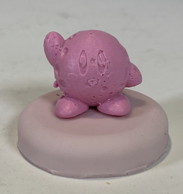
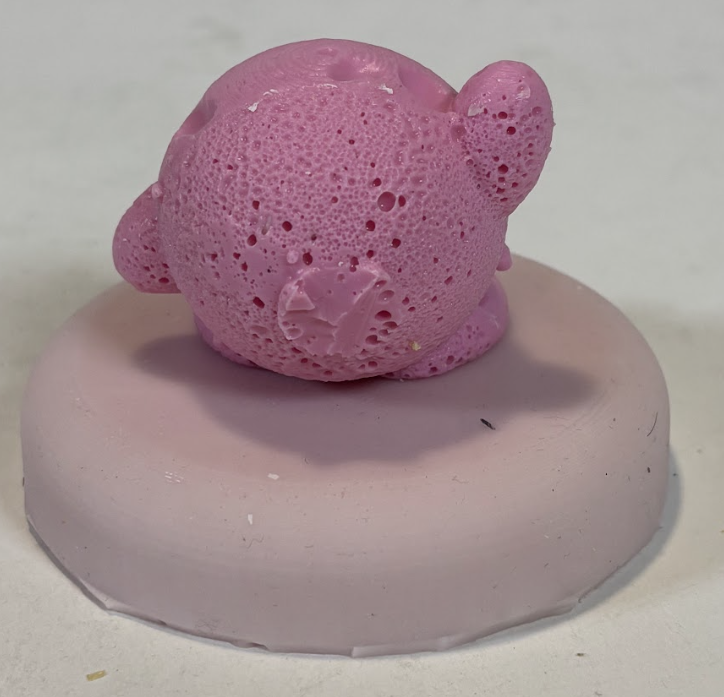
Here are some photos of the final product. Again, there were several holes varying in size due to the consistency of Mold Max 30 as Vio and Maya poured the cast.
Front: Finished Kirby and baseBack: Finished Kirby and Base
Interestingly, you can see the small circumference where the green stirring straw was hot-glued onto the back of the Kirby object.There are many holes on the surface of the Kirby figurine.
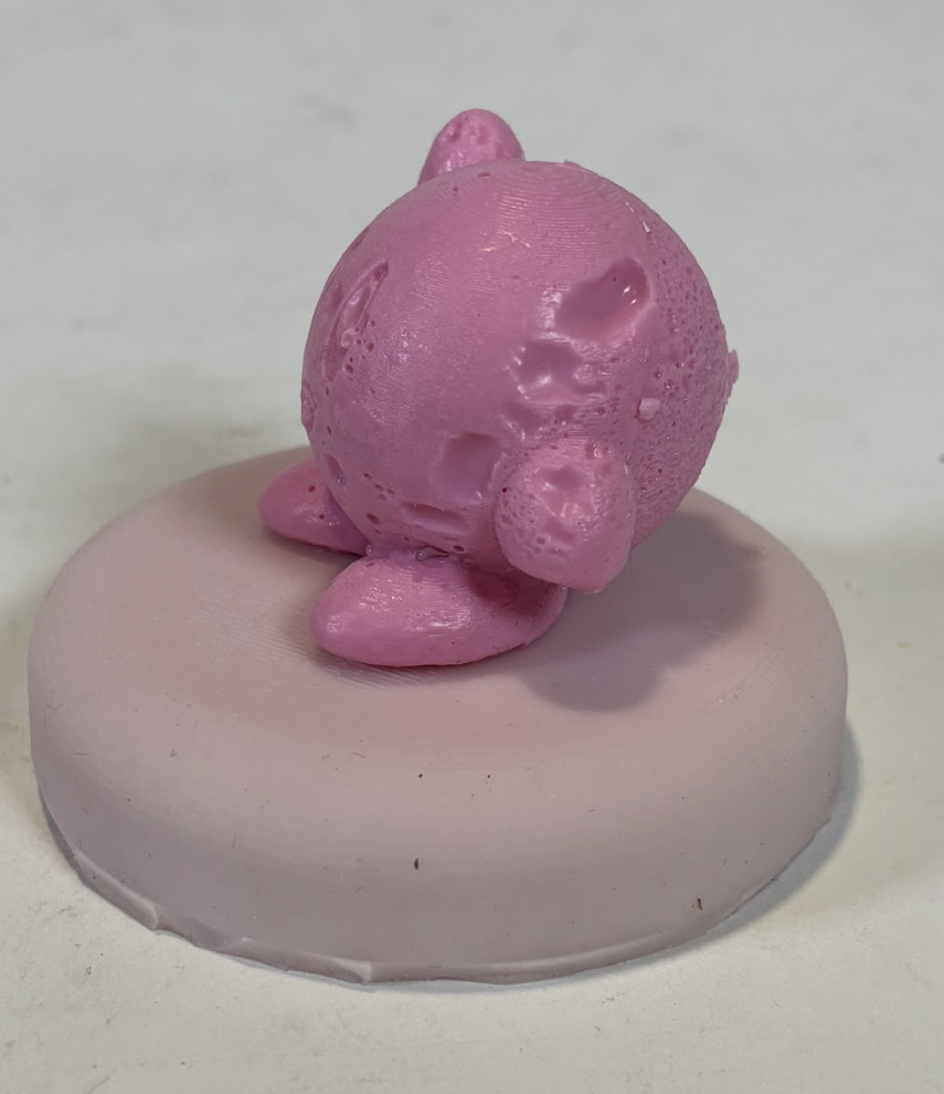
Side: Finished Kirby and Base
Side view of the final Kirby figurine,. 3-4 large, major holes to make her feel better.
From this, I learned that when we pour a very viscous liquid (like the Mold-Max 30), the spout must be very wide to pour. This is because Maya and Vio were struggling to fill the Alja-Safe mold with the Mold-Max material. The Mold-Max material choice was a mistake on my end, because Mold-Max is a molding material and not a casting material. This caused inconsistent pours and our final cast to have many holes.
I wanted to utilize my work from the previous assignment by soldering mechanical switch pins to wires, then attaching those wires to the microcontroller. Essentially, I wanted to make my mini fidget keyboard functional. However, I avoided this idea because I didn’t want to permanently solder wires. Also, I realized through in-class work that many of the sensors (humidity and temperature, ultrasonic distance) were finickity, and often wouldn’t report the correct output.
To design around this, I used the buttons provided with the microcontroller kit to replace the keys. Using the buttons I wanted to design a morse code decoder to type out messages. I thought the button / press sensors would be best to use because they are very intuitive to use, and there were multiple within the kit. Lastly, the buttons were the most similar to keys on a keyboard.
Physical Wiring and Breadboard:
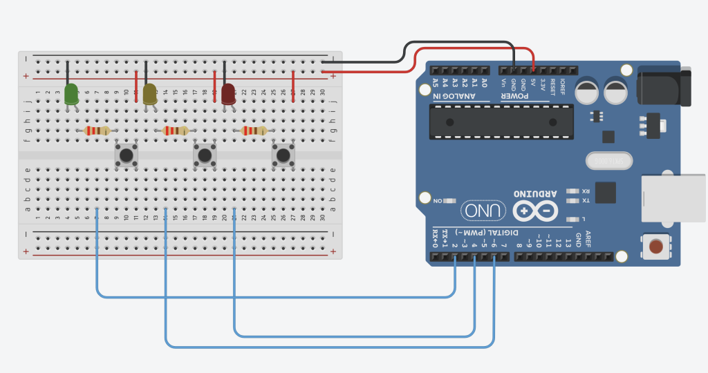
TinkerCAD representation of Breadboard wiring for Morse Code Project
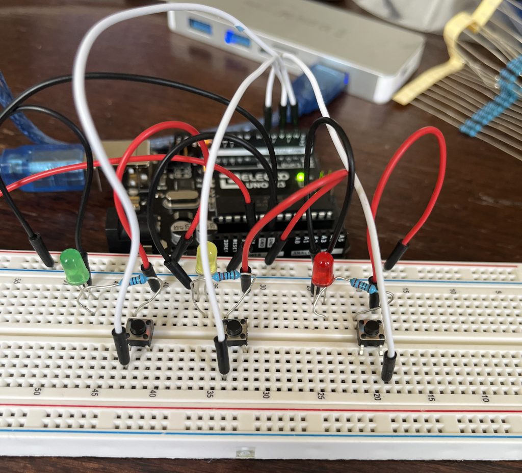
As shown above, each button ‘module’ includes the button itself, a connection to the digital inputs of the Arduino, a 220 Ohm resistor to a colored LED, and then connect back to the positive and negative rails.
When built physically, the Breadboard looks like this:
I chose to include the LEDs to help label what each button does to increase the accessibility of the device. Also, this helps to show when the button is pressed to have visual confirmation that of the button’s state. This is done solely through the wiring, as pressing down the button completes the circuit and allows charge to flow through the LEDs. In other words, there is no communication between the LEDs and Arduino microcontroller.
Coding Process:
I decided to write the code for the main input button first. From there, the same coding structure was copied for the other two buttons, just adding different functions within the if statements. Below are some snippets of the code I developed that are relevant to explain the overall flow of the code, without providing every detail. If you are interested in the full code, please see the Box Drive for the available final code.
Coding Initial Variables
 const int buttonPin1 = 2; // Button Number 1 Input
  int button1State = 0;     // Button Status (0/1)
  int button1Press = 0;     // Time of button press
  int button1Release = 0;   // Time of button release
  int button1Duration = 0;  // Time between press and release
  int button1PreviousState = 0; // Placeholder to avoid unwanted presses
  int CurrentTime = 0;      // Used to count internal time, time since code started


---

int Letter[5];           // integer array to hold dots and dashes
  int CurrentLoop = 0;     // loops through dots and dashes in Letter when translating
  String CurrentWord;      // Output String

// Morse Code Arrays
  char* AlphaNumericals[36] = {"A","B","C","D","E","F","G","H","I","J","K","L","M","N","O","P","Q","R","S","T","U","V","W","X","Y","Z","1","2","3","4","5","6","7","8","9","0"};
  int MorseCodes[36] = {12000,21110,21210,21100,10000,11210,22100,11110,11000,
12220,21200,12110,22000,21000,22200,12210,22120,12100,11100,20000,11200,
11120,12200,21120,21220,22110,12222,11222,11122,11112,11111,21111,22111,
22211,22221,22222};
The section above the dividing dashed lines is from the Button 1 variable setup. Please note that the “buttonPin,” “buttonState,” “buttonPress,” “buttonRelease,” “buttonDuration,” and “buttonPreviousState” are then copied as variables for Buttons 2 and 3. The only difference is the number within each variable name.
Then the Letter[5] integer array holds the sequence of dots and dashes for a single letter, the CurrentLoop is to count which index within the Letter[5] array is currently changing, and the CurrentWord is the string that is printed to the Serial Monitor.
Finally, the morse code arrays are two arrays (AlphaNumericals being a character array and MorseCodes being an integer array). Note that these arrays are used to translate the inputs codes from the user into letters and numbers. Each sequence of 5 numbers within MorseCodes translates to the corresponding index of AlphaNumericals. The matching indexes are later used to translate and generate the correct letter or number.
Setup Void Function
Establishes the pinModes and inputs of all three buttons, and beings the Serial Monitor. Furthermore, the initial instructions on how to use the program are output here. Below are the instructions, not the code for the instructions, for usage:
Morse Code Instructions
-----------------
Use the Left Green Button to input your morse code, a press of less than 0.5 sec is a dot (.),
and a press of more than 0.5 sec is a dash (-)

Wait until the letter has been printed before inputting the next letter.

Press the Middle Yellow Button for 0.5 sec to add a Space.

The Right Red Button is for Backspace and Delete. Press it more than 0.5 sec to backspace,
and more than 2 sec to delete the message

Happy Morse Coding!
If you need the instructions again, press the Middle Yellow Button for 1 sec.
The abbreviated instructions are as follows:
Abbreviated Instructions              // Print out instructions--------------------
Left Green Button:
< 0.5 sec = dot '.'
"> 0.5 sec = dash '-'
Middle Yellow Button:
> 0.5 sec = space
> 1 sec = Instructions
Right Red Button:
> 0.5 sec = backspace
> 2 sec = delete entire message
--------------------
– Sense the downstroke – Read time of press, and set PreviousState variable
– Sense the upstroke – Read the time of release, and set PreviousState variable
– Calculate duration of press
– if press is more than 0.5 sec., enter a ‘2’ into Letter[5] array for a dash ‘_’, increase index
– if press is less than 0.5 sec, enter a ‘1’ into Letter[5] array for a dot ‘.’, increase index
Here, I wanted to create a system that would time the duration of the user’s presses. This is important to differentiate between dots and dashes. The following code details the outline structure for Button 1. However, the coding structure for Buttons 2 and 3 are similar to find the timing. However, the executables for each are different.
Generally, the structure is as follows: the program only senses the time of the downstroke if the previous state was the opposite state. This is to ensure that holding down the button only reads as one time (at the beginning of the hold). For the downstroke (when the current state is high and previous state was low), record the time and set the ‘PreviousState’ variable to the current state (high). Then, when the button is released on the upstroke, again sense the time that the button is released. Again, set the ‘PreviousState’ variable to the current state (now low). Then, define a variable that is how long the button was held down for. If the duration is greater than 0.5 sec (500 milliseconds), this is registered as a dash ‘_’, and store this in the current index CurrentLoop variable into the Letter[5] array. Alternatively, if the duration is less thant 0.5 sec, this is registered as a dot ‘.’ and again stored into the Letter[5] array. After each input (dash or dot) is saved into the Letter[5] array, add 1 to the current loop. This is to make sure that the subsequent input does not override previous inputs.
Automatic Wait Time and Morse Code Translation
Then, I created an automatic wait timing before the program translate the current Letter[5] array into a letter or number. This means that if X-seconds go by without any user input, the translation code is run. However, the user has X-seconds to add additional inputs to their current code. I did this by again using the intrinsic timing system within Arduino.
CurrentTime = millis();
  int button1Pause = CurrentTime - button1Press;
  if (button1Pause > 3000 && Letter[0] != 0) {

    int CurrentCode;
    int Let = 0;
    for (int j=0; j<5;j++) {
      Let = Let * 10 + Letter[j];
    }

    for (int i=0; i<36; i++) {
      CurrentCode = MorseCodes[i];
        if (CurrentCode == Let) {
          Serial.println("");
          CurrentWord = CurrentWord + AlphaNumericals[i];
          Serial.println(CurrentWord);
          Serial.println("");
        }
    }
    for (int i=0; i < 5; i++) {
       Letter[i]=0;
    }
The code above takes the time of the previous user’s inputs and compares it with the current time. Then, it subtracts the two to find the length of the pause, and the time since the last press. Following, if the pause time is greater than 3 seconds and the Letter[5] array is not empty, the following code is executed. The emptiness of the Letter[5] array is done by checking the first index of the array. If the first index is 0, then the user has not input any dots or dashes, and the following code is skipped. If both conditions are met, the integer Let is created. the next for loop translates the Letter[5] integer array into ‘Let’ integer. This step is crucial for the following Morse Code translation because of the ways the dots and dashes are currently stored. The Letter[5] integer array stores the integers as separate numbers, such as {1,2,3,4,5}, while the Let integer must be in {12345} to be compared to the MorseCodes array. So, a commonly-used translation method of multiplying by 10 then adding the next letter was implemented. To visualize this:
Letter[] = {1,2,3,4,5}
Let = 0;
Expanded Loop:
Let = 0 + Let[1] = 0+1 = 1
Let = 1*10 + Let[2] = 10+2 = 12
Let = 12*10 + Let[3] = 120+3 = 123
Let = 123*10 + Let[4] = 1230+4 = 1234
Let = 1234*10 + Let[5] = 12340+5 = 12345
Note that this is not code within the Arduino code file, just a visualization of what happens within the loop. Also, this is why the dash is stored as ‘2’ and dots as ‘1’, instead of as ‘1’ and ‘0’ respectively. If the dot input was ‘0,’ the empty spaces of the Letter[5] array would be empty, and the above calculation would not be possible.
Next, the program takes the new Let integer and compares it with the the Morse Code array that was defined in the variables section. Here, the program loops through 0 to 36 and checks for which integer within MorseCodes matches with the Let integer. If the two integers are equal, the correct code is found. Then, the corresponding AlphaNumerical character (A-Z, 0-9) is concatenated onto the CurrentWord String.
Finally, to reset the code and prepare for the next sequence of inputs, the Letter[5] array is reset to 0. Furthermore, the CurrentLoop variable is reset to 0, so that the program can recognize the next set of inputs.
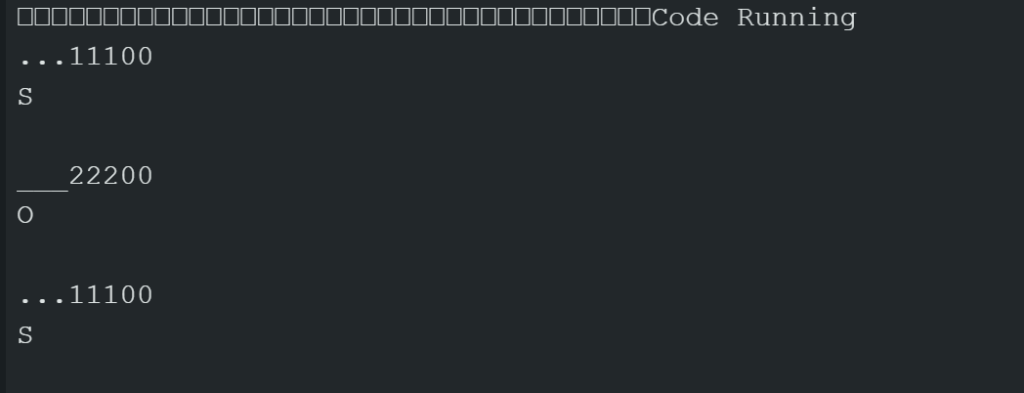
With this, I was able to type out letters!
Screenshot of Arduino Serial Monitor Output. Shows the dot-and-dash input, the integer version of the dots and dashes, then the letter translation of the integer.
Buttons 2 and 3 – Space and Backspace
The same button timing structure is repeated for buttons 2 and 3. Note that for these two buttons, their position is switched between the Arduino Code and Breadboard. I had first written the code for backspace, then the code for adding a space. So, button 2 within the code corresponds to the Right Red button on the Breadboard, and button 3 corresponds to the Middle Yellow button. I had made this order change because it felt most logical to have the Delete and Backspace button furthest from the input button.
For button 2, which is the delete and backspace button, if the button press duration is greater than 2000 milliseconds (2 secs), the CurrentWord Variable is set to “”, which is an empty String. If the button press duration is greater than just 250 milliseconds (0.25 sec), then the code removes the last letter of the CurrentWord string by the following code:
Here, the LastLetter integer is assigned to the length of CurrentWord minus 1. Then, edit the string using String.remove(Index) formatting to remove the character at the last index of the string. Finally, output the current word.
For button 3, which is the space and abbreviated instructions code, the same timing structure is used to determine the length of press of the button. When the button 3 is pressed for more than 1000 milliseconds (1 sec), a series of text is output as the abbreviated instructions. If the button is pressed for more than 250 milliseconds (0.25 sec), and empty space string is added onto the end of the CurrentWord String, and the current word is output.
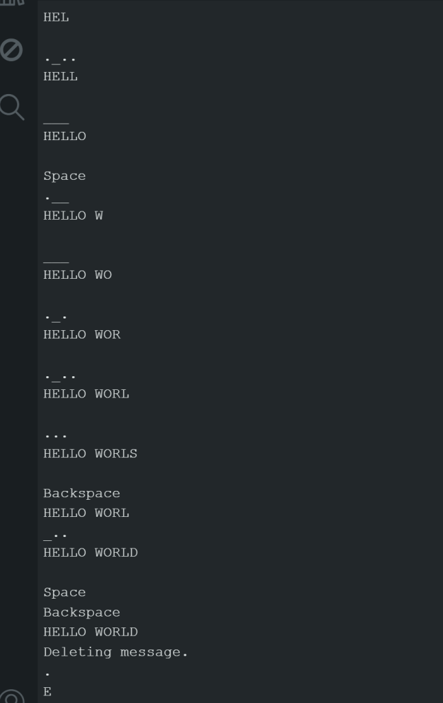
With this, I was able to write out a test with spaces and utilizing the backspace function:
Screenshot of Arduino Serial Monitor Output. Shows the dot-and-dash input and the output phrase after each dot and dash. Also includes the ability to add spaces and backspace.
Reflections:
Difficulties and Challenges
When designing this code, I had created multiple versions to track the progress and an initial pseudo code to outline the code. In past versions, I had changed the Serial Monitor output to confirm the piece of code I was currently working on. For example, when I was first designing the dots and dashes inputs, I would have the output only show the _ and . that corresponded with the inputs.
However, some errors within the code can occurs. For example, if the buttons on the Breadboard are slightly tilted or not fully placed in, this can cause more bouncing. Bouncing is when the button stem physically bounces, causing constant and unwanted inputs. There are pieces of code online to prevent the bouncing effect, but I found that slightly adjusting the metal button pins so that there was no empty space between the bottom of the button and the Breadboard prevented bouncing.
Overall, I struggled somewhat to understand the data structures within the Arduino (and C++ language). These structures were different from the ones I had previously used in MATLAB, so it was difficult to understand their usage and specifications. For example, a character is a single “A,” while a character array can be {“A” , “B” , “C”} or {“ABC” , “DEF” , “GHI”}. An integer can be “1” or “12345,” while an integer array can be {“1” , “2” , “3” , “4” , “5”} or {“123” , “456” , “789”}. Furthermore, the indexing began at 0, while MATLAB begins at 1.
When using the microcontroller, I realized that the major limitation of the board is that your designs are limited by the sensors and parts within the kit. However, you could also buy whichever parts you would want to use for a project. One major advantage would be that the board can be changed and altered easily. For example, I added the LEDs without prior plan to do so because I thought it would be a good physical indicator for when a button is pressed.
Real-World Usage
While Morse Code is not used often in the present communication, the timing structures around timing a button and comparing integer sequences could be useful. For example, this could be used to add a password onto a safe or lock in Morse Code. As a side effect, I have a fairly strong basis of Morse Code if I’m ever in an emergency situation that requires Morse Code to communicate. Not too sure if that will ever happen, but who knows what future challenges will bring. Maybe I’ll be on a survival TV show and need Morse Code.
If I had more time for this project, I would have liked to solder wires to my previous laser cutting project switches. Then, I could use my mini-keyboard as a Morse Code input.
Citations and Datasheets:
I had relied heavily on Arduino forums and online discussions to find people with the same or similar problems as myself. Through this, I found that commentors on these forums can be really sassy.
And also this example Morse Code Project from Arduino. However, this project did the opposite of mine- by translating letter inputs to an LED flashing sequence.
I did not utilize any datasheets for this project, as I had mainly relied on forums and discussion boards. However, I’d like to point out the Arduino UNO R3 Data sheet, which is similar to the board used for this project and a very comprehensive guide on using and coding push buttons.
Provided Code:
If you would like to recreate this design, please see the Box Drive folder for the full code. Please make sure that the buttons are fully and comfortably placed into the sockets, or bouncing will occur. If bouncing does occur (a constant ‘dot’ input that won’t stop), adjust the four pin legs of the push button until the bottom of the button is flush with the breadboard.
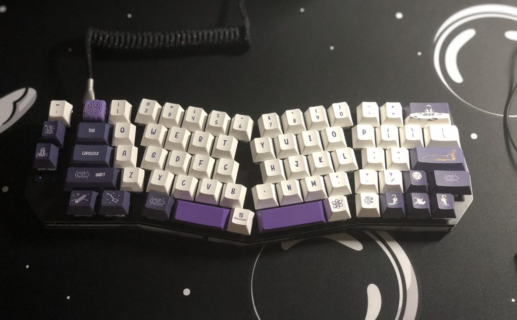
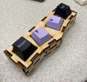
For this homework assignment, I wanted to make a fidget toy (perhaps translatable into a keychain) of an mini-Alice layout mechanical keyboard.
As background information, mechanical keyboards use mechanical switches, which include a spring, top and bottom housing, stem, and metal leaf. For further detail on switch anatomy, click here. Importantly, switch anatomy and sizing is standardized across manufacturing companies, so they can fit into any hole that is the correct size. However, people can be very particular regarding the details of a switch and it’s impact on the keyboard’s sound and feel.
An Alice layout keyboard is slightly slanted toward the middle and is meant to promote more ergonomic wrist positions while typing. If you place your hands comfortably on a keyboard, you might find that your index finger rests on a row below your middle and ring fingers, with your thumbs positioned below on the space bar. In other words, your fingertips may not rest all on the same row of the keyboard, to which an Alice layout keyboard is meant to address. A typical Alice layout is shown below, with variations in escape keys, inclusion of arrow keys, knobs, etc.
Example of a Full Alice Keyboard, from Keychron.com
In total, I wanted to make a small fidget toy with four mechanical switches in the shape that represents an Alice keyboard layout (because it’s my favorite). My current keyboard is shown below:
Amanda’s Alice layout mechanical keyboard
Design Sketches
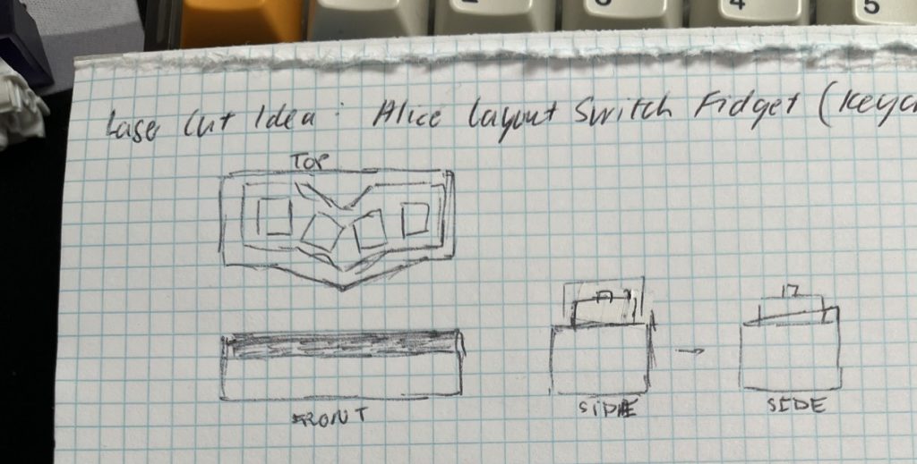
To start, I sketched a loose Top, Front, and Side views of my fidget toy, noting the slanted middle of the design.
Sketch 1, Not to scale Top, Front, and Side Views. Holes are loosely drawn, general concepts
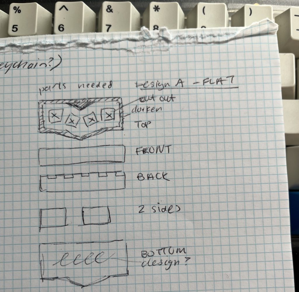
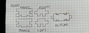
Then, I sketched two possible designs: the first where the top of the toy was flat, and another which was slanted. These sketches included Top, Front, Back, Sides, and Bottom designs.
Design A – Flat
Sketch 2.1 – More thorough sketch of toy, with flat top. In the side views, the top of the side panels are flat.
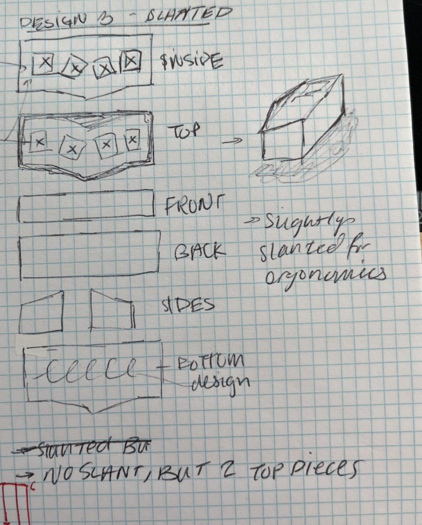
Design B – Slanted
Sketch 2.1 – More thorough sketch of my toy, with a slanted side. Includes isotropic view. Slant design is easily seen in the side views.
I ultimately chose the flat top to simplify the CAD work and laser cutting processes. Mainly, by keeping the top of the toy flat, the finger joints between the top and connecting pieces would be at 90 degrees. If I had chosen a slanted design, these joints would not be right angles, which would make the cutting and assembly of the parts more difficult.
Sketch 3 – Finger joint notes from linked Youtube Video without a top layer
Notably, this sketch does not include the inside-tier plate, of which I designed for in the CAD process.
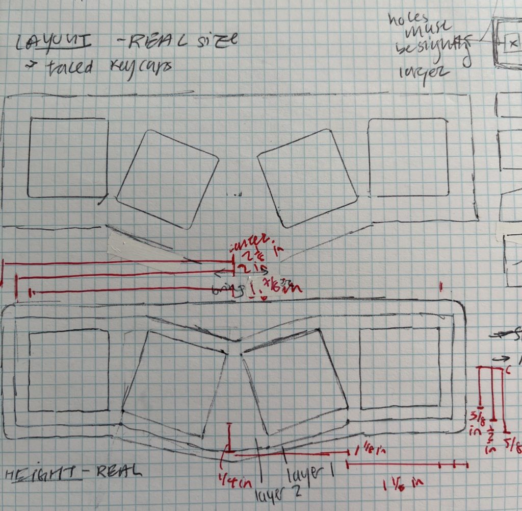
Next, I created a more refined layout with one-to-one ratio dimensions (the dimensions of the final toy would be the same as the drawing). I did so by tracing the outline of keycaps in the locations and slants that I wanted. The first version of this sketch (top) was too far spaced in the middle. This problem was solved in the second sketch (bottom), with less space in the middle. Using this sketch, I measured approximate dimensions of the final toy. To note, the design is symmetrical, and lines appearing to be center lines should be assumed to be centered.
Sketch 4 – Real size sketch of fidget toy, Dimensions in red lines are in inches
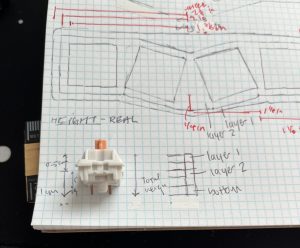
Lastly, I wanted to layout the real height a mechanical switch, and begin ideation on the thickness of layers and the distance between them. I needed these dimensions to be correct in order to fit the switch into the toy.
Sketch 5 – Dimensions and anatomy of a standard mechanical switch
With a more refined sketch in hand, I then transferred this design into AutoCAD.
Common Dimension Conversions
Below are some common dimension conversions between imperial and metric units for your convenience.
Imperial
Metric
0.39 inches
1 cm
0.20 inches
0.5 cm
0.118-0.12 inches
3 mm
Table 1 – Conversion of imperial and metric units commonly used below.
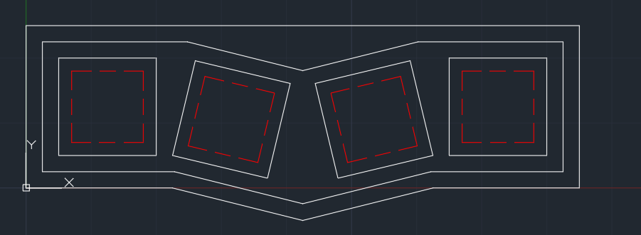
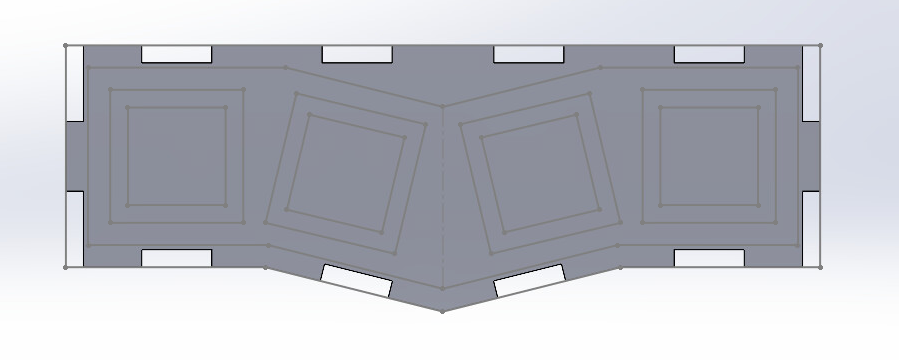
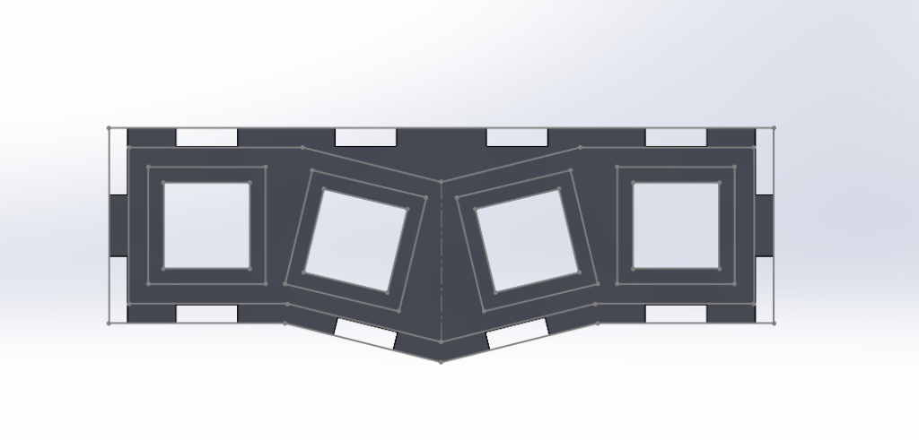
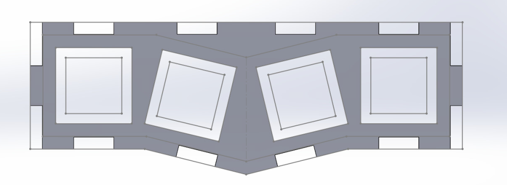
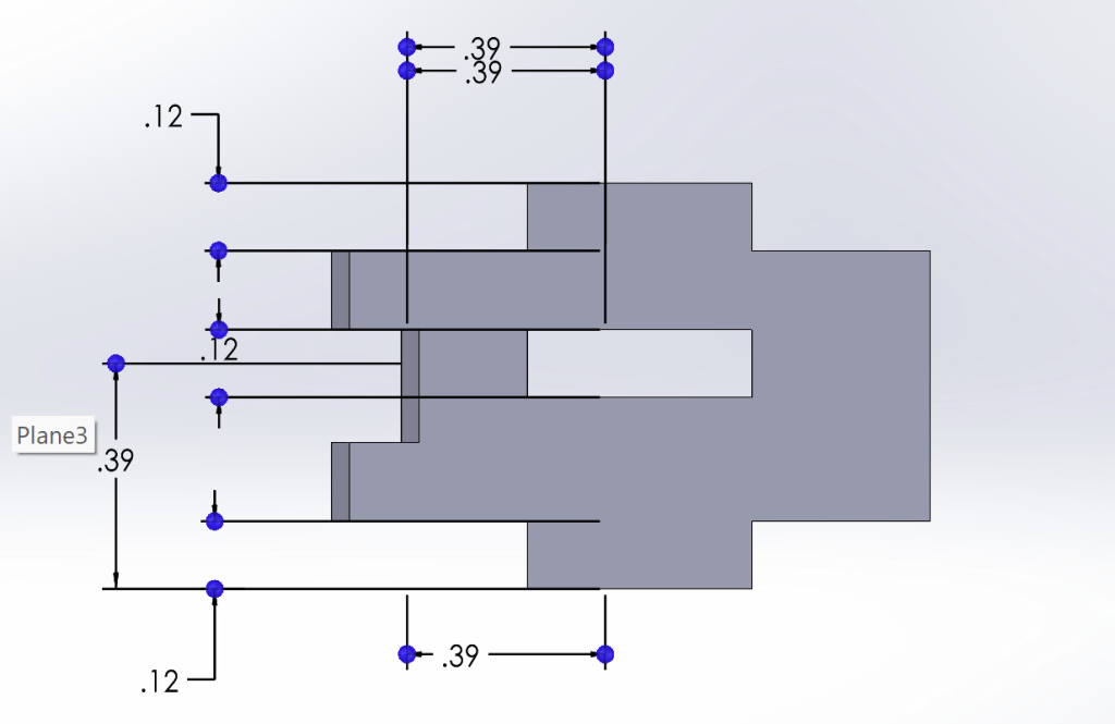
CAD Sketch 1 – Digitalization of initial sketches, with red dashed lines representing the inside plate
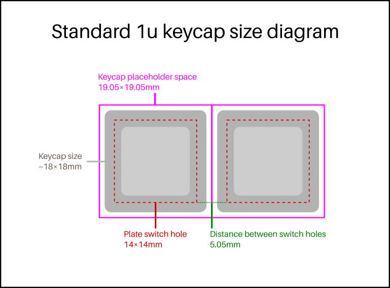
Generally, parallel white lines were made by an offset of 3mm (0.118 inches). In the dashed red lines were holes made to fit the mechanical switch. The white boxes directly surrounding the dashed white lines were made to fit the keycaps. The red dashed boxes were ~14×14 mm, while the white keycap holes were ~19x19mm. These two would be made into two different layers.
Initial Sketch into Three Dimensional Parts
At this point, I realized I had made a mistake by starting the initial CAD in AutoCAD, rather than SolidWorks. I then had to transfer the AutoCAD 2D drawing into SolidWorks as a sketch. Then, I gave the sketch height using an extrusion, then cut out the middle to resemble a typical Alice keyboard case. Note that for this project, the displayed dimensions are in inches.
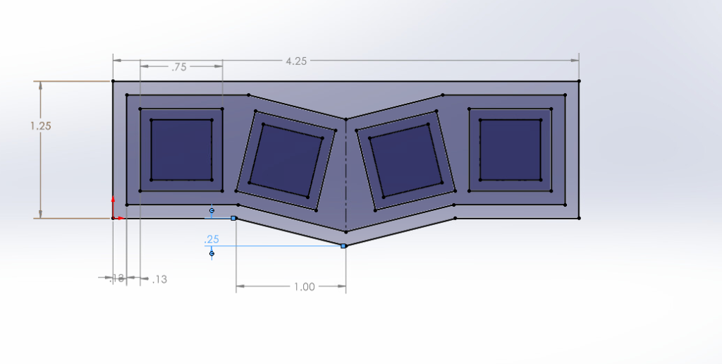
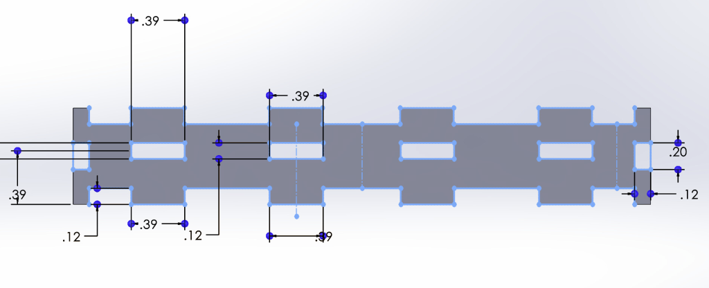
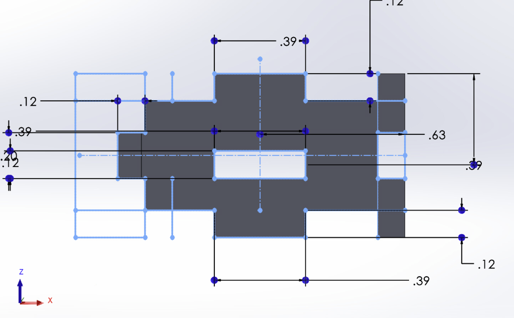
Displayed below are the total width and length, width of boxes, offsets between parallel lines, and the dimensions of the tilted middle. Notably, one thing I had missed was the degree angle of this tilt.
CAD Sketch 2 – Translation into SolidWorks and dimensioning
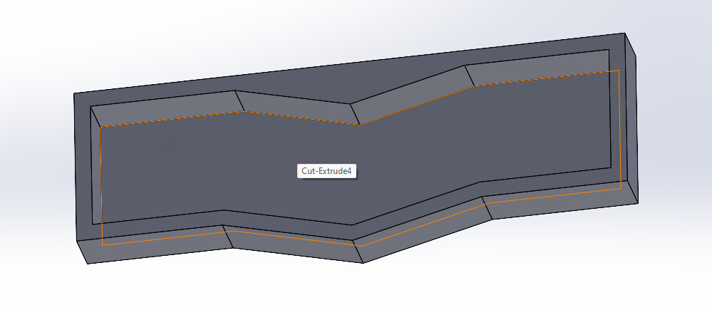
I then extruded this into a case-like part with a height of 1.5cm, as determined by the height of a switch (~1cm). Later, I added another 3mm in the opposite direction of the original extrude to create finger joints that accommodated the added height of the top plate.
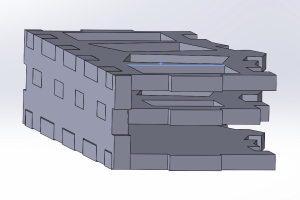
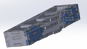
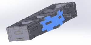
Extrusion of Sketch – Used to give a 3D visualization of an Alice layout mechanical keyboard
This three-dimensional extrusion would be helpful moving forward, as I wouldn’t need to redefine the dimensions of the back, side, and front panels.
Top, Bottom, and Inside Plates
I first started with the Top, Bottom, and Inside Plates of the design because they were all similar in shape and would help me to visualize the rest of the design. For these three, I had chosen the inlet vs. outlets of the finger joints based on the research I had done earlier. Throughout the design, I had used finger joint rectangular holes that were 1cm in length and 3mm in width to fit the 3mm birch wood I was planning to laser cut from. If not specified, assume these dimensions for finger joints.
CAD Sketch 3 – Bottom plate of fidget toy
Shown above is the bottom plate, which has no holes cut out but has inlet finger joints on the north and south sides, then outlets on the west and east side.
CAD Sketch 4 – Middle layer plate of fidget toy
Above the bottom plate would be the inside, mechanical switch plate with ~14×14 mm holes. To make this, I had copied the bottom plate and cut out the inner square holes.
CAD Sketch 5 – Top layer plate of fidget toy
Above the middle layer plate would be the keycap or top plate with ~19×19 mm holes. Similar to the two above plates, I had copied the bottom plate and cut out the outer square holes.
Lastly, I extruded of the sketches to a height of 3mm, or the real thickness of the birch panels.
Back Panel
I then designed the finger joints of the back panel, now knowing the placements of the bottom, middle, and top layer plates. Note, the back panel refers to that which is not tilted / in the v-shape.
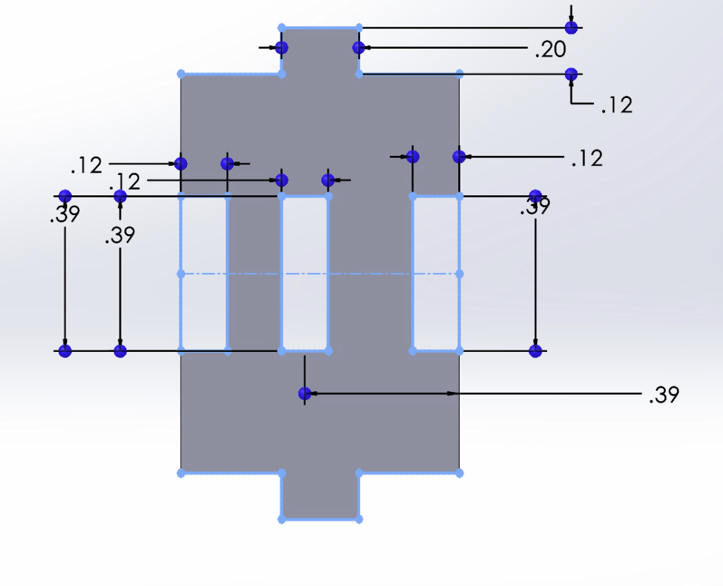
CAD Sketch 6 – Back panel of fidget toy
Notably, there is a finger joint hole in the middle of the back panel to fit the middle layer. This joint hole is centered to 1cm above the bottom edge of the back panel. This is based on information regarding the height of mechanical switches.
From this point on, I began adding the back panel with the bottom, middle, and top plates into a SolidWorks Assembly file. I did this to ensure that the real cuts would fit into the finger joints and holes after laser cutting. Pictured below are the top, middle and bottom plates mated to the back panel.
CAD Assembly 1 – Back panel, top, middle, and bottom plates attached.
At this point, I was relieved because the middle-layer holes in the back panel had fit the 3mm thick middle plate.
Side Panels
The side panels were designed in a similar way, with the same middle layer finger joint hole 1cm [0.39 inches] above the bottom edge. For the side panels, I didn’t need to make different designs for the left and right panels, as they were mirrored and symmetrical. Notably, for the side finger joints (those pictured on the top and bottom of the below sketch, in blue), I used a width of 0.5cm. This is because a full 1cm width would take the majority of the total length.
CAD Sketch 6 – Side panel sketches of a fidget toy
Again, I then inserted two of the side panels into the same Assembly file, and fit them into the finger joints.
Front Panels
Of the finger joints designs I had to make, the front panels were the most difficult. This is due to two main reasons: (1) Because they were the last panels that I designed, they had to fit around the previously built parts and (2) the slanted v-shape of the front post problems in create non-90 degree angle finger joints. To overcome this, I decided to leave the tip of the ‘V’ front shape smooth without finger joints and simply glue them after laser cutting.
Most of this process was checking the existing finger joints of other parts, and fitting the front panels.
I started with the two-non slanted front panels, which almost had a ‘fish’ shape:
CAD Sketch 7 – Front parallel panels of fidget toy design
The above images show that the east and west sides were cut-out inlets, the north and south sides were outlets. This panel also included a middle-layer hole. After creating the right side front panel, I mirrored the design to be the left side front panel.
Again, I inserted the front panel and its mirror design into the Assembly file, mating them to the correct position.
CAD Assembly 2 – Previously attached parts with two front panels
I had the most difficulty with the slanted front panels. I was mainly confused on how I was going to connect them to the previous parallel front panels and to one another. Like previously, I was planning to create one side of the slanted front then mirror it to have the other side. (In total, the front part of the box included four panels to cut).
After much fiddling, I decided on the above design. The slanted front panels would be smooth (no finger joints) at the tip of the ‘V’ shape but include finger joints on all other sides. For this, there were outlets on the north and south sides, and a middle-layer hole consistent with all other parts (back, sides, front). Additionally, there were outlets on the sides facing the other two front pieces.
CAD Sketch 8 – Front slanted panels of fidget toy design
Lastly, I inserted the front panel and its mirror design into the Assembly file, mating them to the correct position. I fit the slanted front panels into the file as well, ensuring that all of the finger joints and holes were well-aligned.
CAD Assembly – Previously attached parts with last two front panels
Laser Cutting
Saving as a .DXF Vector File and Uploading
I saved all of the individual parts from the SolidWorks parts files as .DXF files. I had to select the faces that I wanted create a vector out of.
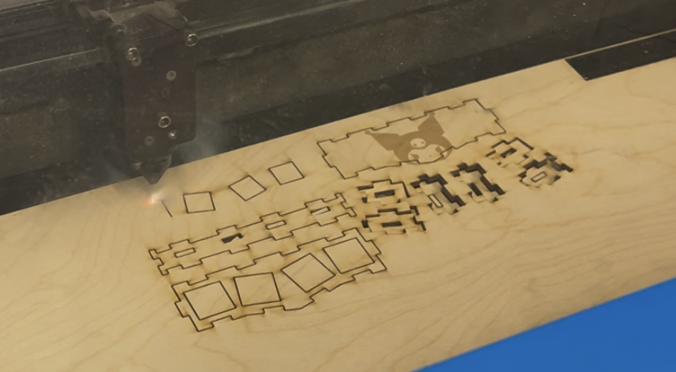
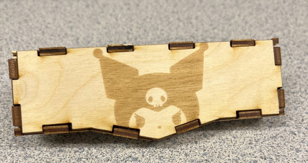
I then uploaded all of the individual parts, total 10 panels, into the Adobe Illustrator. Furthermore, I took an image from online of Kuromi, a cartoon character. I took this image, vectorized it and isolated the part that I wanted to raster on the back of my fidget toy. Through this process, I learned the basics around Adobe Illustrator, grouping/ungrouping lines, erasing lines, etc.
Laser Cutting Procedure
To laser cut, I used the Nolop FAST Facility at Tufts University. I then used the set 3mm birch wood settings at 100% intensity, 15% speed, and 3.00mm width. The Nolop laser cutters are the Universal VLS 3.60 models.
However, I had a lot of difficulty using the purple laser cutter, as the laser cutter would create very thick lines and not cut through the board. (There was a point where I had tested this laser cut five times on the same birch wood plank.) Then, I tried the same on the blue laser cutter, which worked much better, had thinner cutting lines, and cut all the way through.
I adjusted the previous Adobe Illustrator file into the laser cutting software to take up as little space as possible, mindful of the resources I was using. I then added the Kuromi vector image onto the back panel of the toy in grayscale.
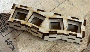
Throughout this process, I recruited the help of a mechanical engineering friend (shoutout Hudson), who said that it was ‘fun’ and ‘like legos’. We started the assembly by attaching the top, middle, and bottom plates to the back panel. Then, we attached the two side pieces, then the front parallel pieces, then the front slanted pieces.
Physical Assembly 1: Laser cut box
There were some finger joints that had cutting malformations that did not fit together perfectly. To adjust to this, we sanded down joints that were extruded too far. Then, for panels that were wiggly, we used super glue to firmly attach the joints. Mainly, we used the glue on the front two slanted panels.
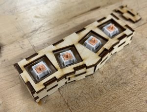
Then, I inserted four Drop Holy Panda V2 mechanical switches into the holes. These fit perfectly, snapping into place firmly. Out of the four, only one square hole had been larger. This mis-cut wasn’t in danger of falling out, but we needed less force to pull it out.
Physical Assembly 2: Mechanical switches added
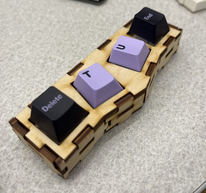
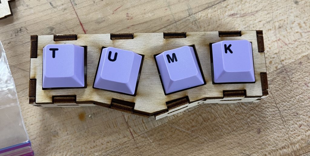
Lastly, I added four keycaps (T,U,M,K), which stands for Tufts University Mechanical Keyboards- one of the clubs I am in!
Physical Assembly 3: Keycaps added
Final image of fidget toy, with alternate keycaps
Final image of fidget toy, back panel details with Kuromi engraving
Reflections
In total, I was pleasantly surprised about this assignment. While using the laser cutting program was frustrating at first, the cutting time was fairly quick and only caught on fire once.
I were to restart the project with my current knowledge, I think I would adjust the ‘order of operations’ that I did the SolidWorks in. I did the most difficult finger joints last, meaning I also had to maneuver around both constraints (surrounding finger joints and slanted angle).
I think that laser cutting is particularly useful for more precise woodworking tasks, compared to handsaw or other tools that are less precise. Furthermore, the laser cutting has a smaller scale and can cut more precise and clear 90 degree corners. However, laser cutting has faults in that there may be slight tolerance issues due to the laser cone shape. Additionally, finger joints and laser cut and assembled parts feel more loose and at-risk of falling of/out. In total, while laser cutting is preferable when fabricating smaller scale objects, traditional woodworking methods are preferable when working on a larger scale and are more stable.
In the future, I would raster around the visible finger joints to create a more cohesive aesthetic. Also, I realized I was missing a raster detail on the top plate.
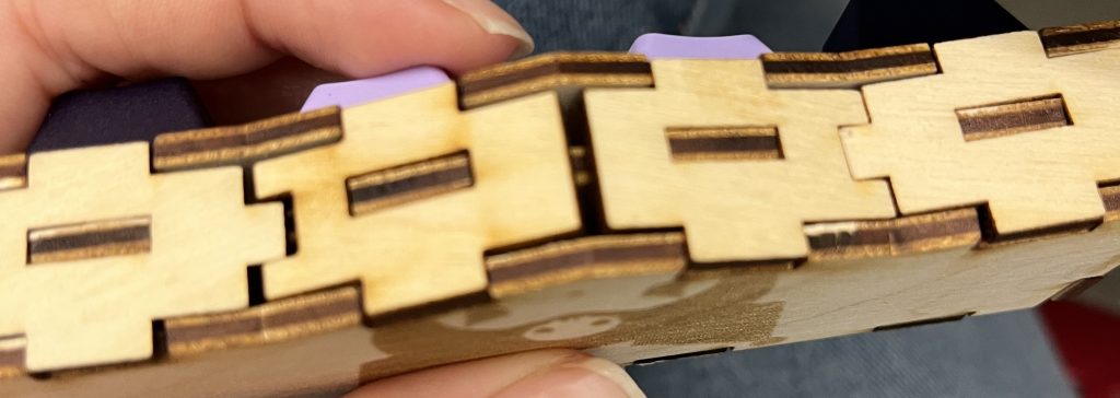
Lastly, during the process of assembling the toy, we had broken some of the more delicate corner joints, pictured below. Also, I made some mistakes while doing the CAD for the front slanted panels, as there were large gaps between the finger joints.
Reflections 1: Misdesigned slanted front panels
I would have to adjust the length of the front panels to make sure that this hole doesn’t recur in future laser cutting.
CAD Files for Use
If you wish to explore/modify/laser cut a fidget toy yourself, please visit this Box Drive that includes all of the .DXF and .AI files to laser cut.
I used this assignment in conjunction with my research laboratory research. I will be printing iterations of the petri dish holder, as detailed in homework 1. To do so, I will be using the FormLabs SLA (stereolithography) 3D Printer in the Timko Lab (Sci-Tech Room 224). This setup includes a FormLabs Form 2 Printer, Wash Bath, and Curing Station, and the prints were made use the FormLab’s Clear Resin V4.
Initial Sizing Print
First, I wanted to print early iteration of the SolidWorks file to test the sizing of the petri dish and how it fit within the chassis, how the petri dish would inside the holder. In essence, this step was a ‘reality check,’ of sorts. While in the process of building in SolidWorks, I decided to print this simplified version:
Step 1 of HW(1.0), Basic Shapes of Petri Dish Holder
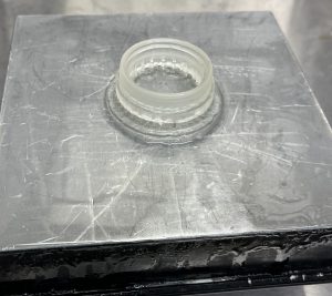
This print took about two hours, then received a 15 minute isopropyl alcohol wash bath, then a 15 minute UV lamp curing process.
Size Testing Print, Note Support Pillars Inside Holder Diameter
After curing the print in the UV lamp, I removed the resin print from the metal printing platform. I used ethanol to degrade the ‘raft’ supporting print, then peeled the print from the metal platform. Lastly, I cut off the thin supports from the print using pliers.
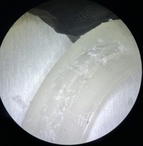
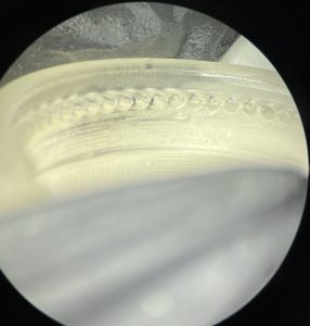
However, I made a mistake while printing this iteration and placed supports on the inside of the petri dish, which made small dents on this inside surface when I cut the supports off. This mistake made the inside of the holder bumpy and malformed, as shown below.
Microscope Image Focused on Malformation due to Print Support Pillars
From this test print, I learned that the outer diameter of the petri dish holder was too large to fit within the chassis, and I had to adjust the final design before printing again.
Adjustments and Optimizations
From here, I needed to slightly adjust the diameter of the petri dish, as the test sizing print was a little too large to fit within the chassis.
Additionally, I wanted to optimize the resin material usage. I did so by minimizing the raft size: raft thickness and support height.
Below is a table with the change in parameters to optimize and a quantitative comparison of material usage and printing time.
Parameters
Before Optimization
After Optimization
Raft Thickness
3.00 mm
0.75 mm
Support Height
5.00 mm
3.00 mm
Raft Type
Full Raft
Mini Rafts
Print Time
1hr 45min
1hr 30min
Resin Used
8.17 mL
5.94 mL
Table 1: Comparison of Optimization Parameters for Printing Settings
Functional Testing Print
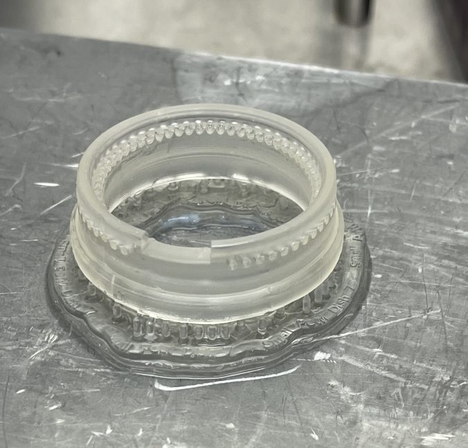
Then, after fixing the SolidWorks design and being mindful of placing support pillars, I had printed the final design of the holder. This corresponds with Step 6 in Homework 1.
Again, I used the same printing, washing, then curing steps. I also used a similar removal process as I have detailed above (add ethanol and let rest before removing from the metal platform, remove supporting pillars.
Before removal, the print looked as such:
Functional Testing Print, After Sizing Adjustment
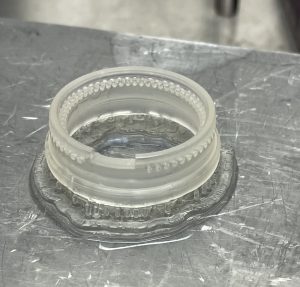
Note that in this print, all supporting pillars are in contact with the bottom surface of the print, in order to avoid the mistakes I made in the testing print. Then, I inspected the print for any major misprints, focusing on the ventilation holes.
Microscope Image of Functional Test Print Focused on Ventilation Holes (1.5 mm Diameter)
Difficulties and Reflections
The most difficult part of 3D printing this holder was to adjust and predict any minute variations in sizing due to errors. Because this print needed very small and precise layers, it was difficult to gauge if the print had any errors until after it was processed (washed and cured). Furthermore, unlike with filament printing, the printed design with SLA printers like FormLab printers require extensive post-printing process that extends printing time.
However, the petri-dish holders (and corresponding chassis) require 3D printing to fabricate, because they cannot be made in-house in any other method. Additionally, the resin for the prints withstand the high temperature and pressure used in autoclaving, thus are viable to be sterilized and used for cell cultures.
Conclusions and Future Directions
Note that while the Functional Testing Print corresponds with the final step as described in Homework 1, it is unlikely that this is the final iteration of the petri dish SolidWorks design or the final print. The design is an iterative process, and there are many design features I have not addressed or have missed. For example, by shrinking the diameter of the upper walls to fit a 35 mm diameter petri dish, there leaves a gap between the chassis and holder. The two are no longer flush, which may be detrimental to the membranous electronic device we are aiming to protect.
In this exercise, the class was asked to engage with the ‘Microcosm,’ or the context, the potential users, and the methods of a design. We started this exercise by imaging a day in our lives, then identifying a problem that we faced throughout the day. For example, my problem was that I had spent too much time in the morning scrolling on my phone. Then, we discussed in partners about the low points of each other’s days and conducted mini interviews to reach the root causes of the problem.
Then, we reframed each problem into an open-ended question in hopes of reaching a potential solution. Rather than a physical solution, what action could we take to resolve the problem? My partner’s problem was that they experienced low energy at the end of the day, so events and classes in the evening were tiresome.
From this, we brainstormed four potential solutions under the following constraints.
Solution Constraint:
Possible Solution:
1. Solution is expensive
1. Invest research into medication that upkeeps energy
2. Solution done tomorrow
2. Take a nap halfway through the day
3. Solution that uses existing product
3. Use meditation apps to help recharge
4. Solution uses robots
4. Make a robot to attend boring meetings in your place
We proposed the four solutions to each other, then received feedback on the possible solutions. From the feedback, we thought of an improved solution. My solution was to dedicate spaces on campus for naps, especially for students who lived off-campus and couldn’t walk back home between classes.
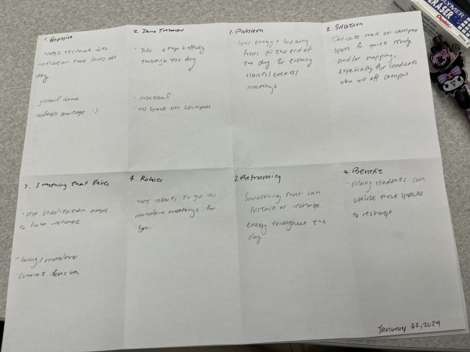
Finally, we made a storyboard to ‘pitch’ our solution. The storyboard included the initial problem, how we reframed the problem, the proposed solution, and the lasting benefits with the implemented solution.
My storyboard was written as such:
1. Problem
My client’s problem was that they experience low energy and lacking focus at the end of the day for evening classes/ events/ meetings.
3. Solution
My solution was to dedicate more on-campus space for quiet study and napping, especially for students who live far away.
2. Reframing
I reframed the problem into searching for a solution that can sustain or recharge their energy thoughout the day.
4. Benefits
Overall benefits include that many students can utilize these spaces, and does not just serve one person.
For this assignment, I decided to extend the work I am doing in research lab.
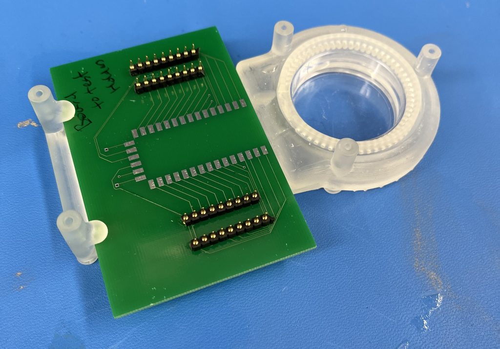
In lab, we are building a chassis/holder to insert an MEA (multi-electrode array) and a petri dish together. A thin membranous device is then placed on top to connect the MEA and cells within the petri. The goal of the device is to make sure the MEA, petri dish, and membrane do not move and break or break contact. An image of the current prototype is shown below:
Photo of Example MEA, Printed Chassis, Printed 40mm Petri Dish Holder, and Petri Dish
However, the holder is current 3D printed for a specific size of petri dishes. This size is no longer available for use in our lab, and we now utilize petri dishes with a smaller diameter (35 mm diameter). To adjust to the size change, I will model and 3D print (Homework 2) a larger model for the petri dish.
The holder was designed with a insertable petri dish holder, which was meant to allow the user to remove the petri dish for microscopy or other assays. This is a positive design aspect, because I can use the existing chassis and just adjust the petri-dish holder.
Design Needs
The newer version of the petri-dish holder must securely hold a 35mm petri dish, and fit into existing chassis.
The design must allow for airflow between the environment and the interior of the petri dish for gas exchange.
The design must allow for the petri dish top to be placed on top.
Drafting and Measurements
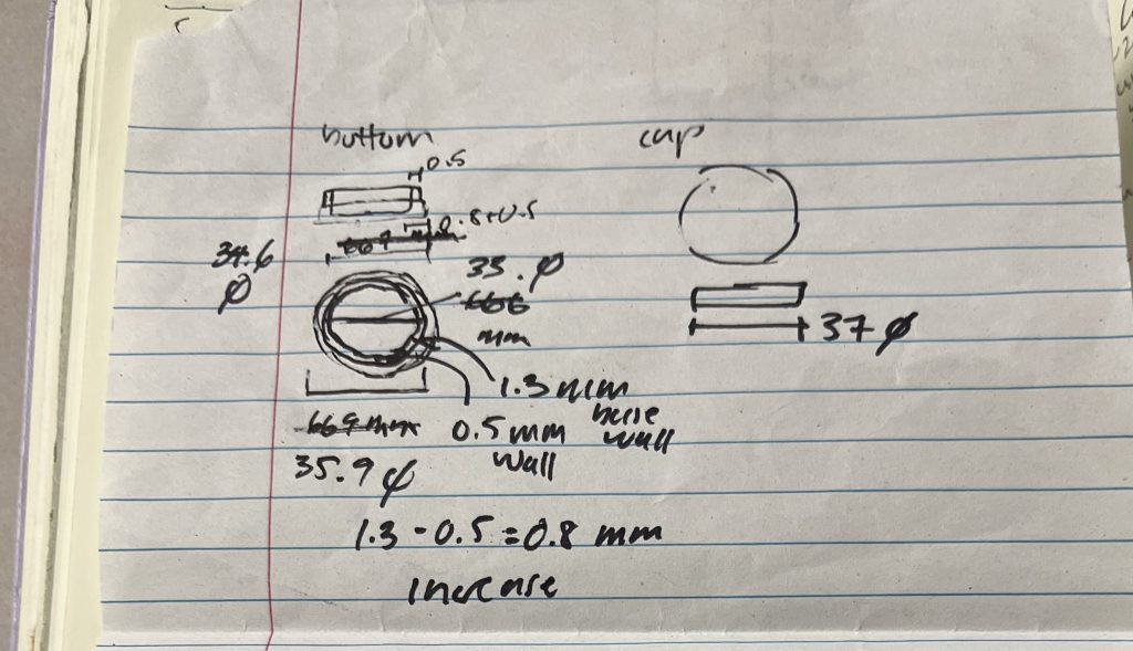
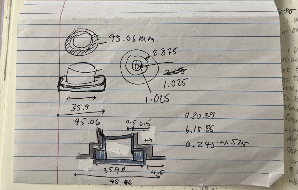
To start, I measured the multiple diameters of the larger petri dish and the smaller petri dish, the current petri dish holder, and the MEA chassis. Shown below are the initial sketches, measurements and existing dimensions.
Initial Sketches of 35mm Diameter Petri Dishes, Side and Top View. 35mm Diameter Petri Dish Cap
35mm petri dishes have a profile akin to a two-tiered cake. The bottom half of the petri dish juts out with a greater diameter, rather than being a straight wall. I measured the thinner upper walls and the thicker lower walls of the petri dish. I also measured the height of the thinner and thicker portions, and the total height of the dish.
I measured the existing design diameter, the diameter of the chassis insert hole, and the change in diameter between the larger and smaller dishes.
Initial Design
Luckily, the design and needs to be addressed were already accommodated in the larger design. So, the major aspect I needed to address was the change in diameter. My solution was to add a ‘skirt’ at the circumference of the design to fit into the existing hole.
Sketch of Initial 35mm Petri Dish Holder Design, with Added Skirt
SolidWorks Process
The design was made in SolidWorks using mmgs (millimeter, gram, second)and ANSI measurement settings.
Step 1: Basic Shape Outlines
I started the holder with two extrudes of circles. The most outer walls are meant to close the gap between the petri dish and chassis hole. The innermost diameter is meant to fit around the outside thick wall of the petri dish (~37mm diameter). Note that the inside is smooth, and the inside wall does not change in diameter. This will be a crucial difference in the next step.
Step 1: Basic Shape of Petri Dish Holder
Step 2: 3-Tiered Interior
Next, I added a third ‘tier’ or layer onto the holder using extrude functions. Notably, this next step does not change the total height of the design. Furthermore, this step adds three layers into the inside of the design; however, the outside of the design is still two layers. The top-most layer will be changed in the following steps.
Step 2: Under View of the Design, All Three Layers are visible
Step 3: Upper Lip Groove
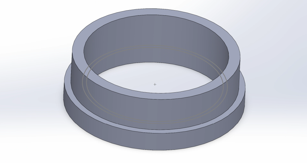
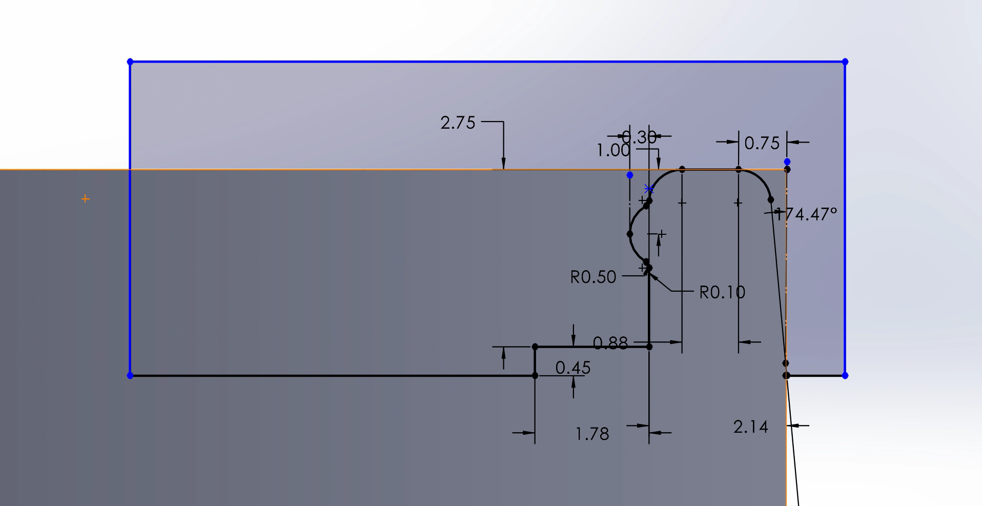
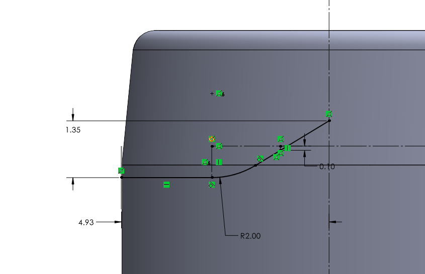
Next, I added a lip to the uppermost lip of the holder using a revolved cut. This lip makes the holder’s top less sharp, and more usable in lab. Note that this design is based on the previous and larger design, but that the design and sketch do not change with the holder size. However, I wanted the current and previous design to be consistent, so implementing the new design to other lab members would be seamless. The SolidWorks sketch is imaged below:
Step 3 Sketch: Design the Upper Lip of the Holder Through a Cross-Sectional View
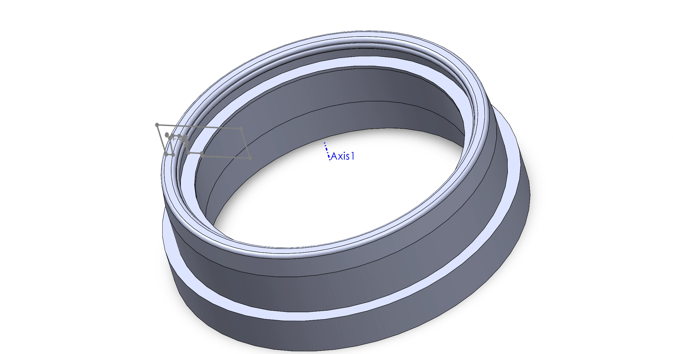
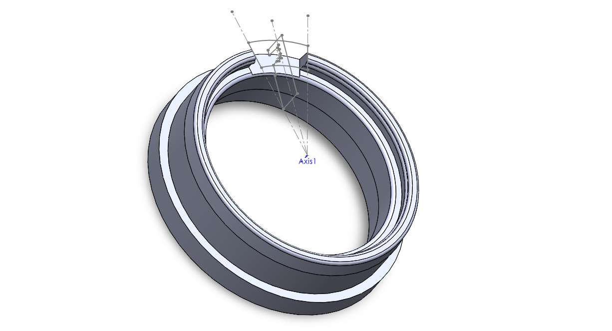
Then, I used a cut and revolve feature to apply this sketch to the entire circumference of the holder. I wanted to used a revolving sketch because this feature allowed me to add a detailed cross sectional profile of the lip. I revolved the sketch around Axis 1, as seen in the image below.
Step 3 Cut-Revolve Feature: Revolve the Step 3 Sketch Around Holder Circumference
Step 4: Membrane Ramp Cut Out
Next, I needed to make a cut-out for the membrane to rest in as it connects between the MEA and interior of the petri dish. This feature is crucial because the device is delicate, and sudden up and down turns would increase the risk of ripping the membrane. For example, without the ramp cut-out, the membrane would have to rest on top of the lip made in Step 3, then turn sharply to rest in the petri dish.
To do so, I sketched a rounded-trapezoidal shape that would cut out a 30 degree ‘slice’ of the lip. I wanted the ramp to slope downwards as discussed above and needed the start of the ramp to be level with the rest of the chassis. I made a new plane that was parallel to the top of the newly-created lip. In the sketch, I made two concentric circles, that were also concentric to the rest of the holder. I kept the circle centers at the origin so I could keep this consistent. However, the radii of the two circles were arbitrary as long as they surrounded the upper lip. Then, I made lines that were 30 degrees apart, and used these to create a closed shape. Lastly, I used a extruded cut feature to create this cut-out, as pictured below.
Step 4: Cut Out Ramp for Membrane
Step 5: Ventilation Holes
The next step was to create ventilation holes for continuous gas exchange between cells and the environment. To do so, I used a cut-sweep feature such that the hole would point upwards when closer the center. Adding an angle to these hole was crucial because we could not risk unknown fluids (ethanol, water, etc.) from easily entering the dish. Also, the holes were cut just under the Step 3 lip.
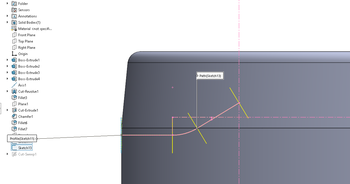
A cut-sweep feature uses two sketches: a path and profile sketch. The profile sketch is simple; a 1.50 mm diameter circle, which was 10.30 mm from the bottom surface of the holder. However, the path sketch was more complicated, as it was designed in the previous (larger) version of the holder. The path sketch consist of an arc with a radius of 2 mm, and two tangent lines. I defined the path length and tile using a total height increase and total length of the path. The sketch details can be found below.
Step 5.0: Path Sketch to be Used in Cut-Sweep Feature, with Dimensions
SolidWorks then automatically calculated the profile sketch along each turning point on the path sketch, as the tilted angle can be seen in below. Each short, yellow line represent the profile sketch. Each yellow line is a 1.50 mm diameter circle in the plane perpendicular to the screen, as in the plane is coming toward you vertically.
Step 5.1: Path Sketch for Cut-Sweep Feature of Ventilation Holes
Step 6: Circular Pattern for Ventilation Holes
Next, I wanted to make a circular pattern for the ventilation holes to be repeated around the holder’s lip circumference. To do so, I used a 360 degree circular pattern to repeat the cut-sweep feature from Step 7. I then manually removed the six holes that would interrupt the ramp made in Step 4.
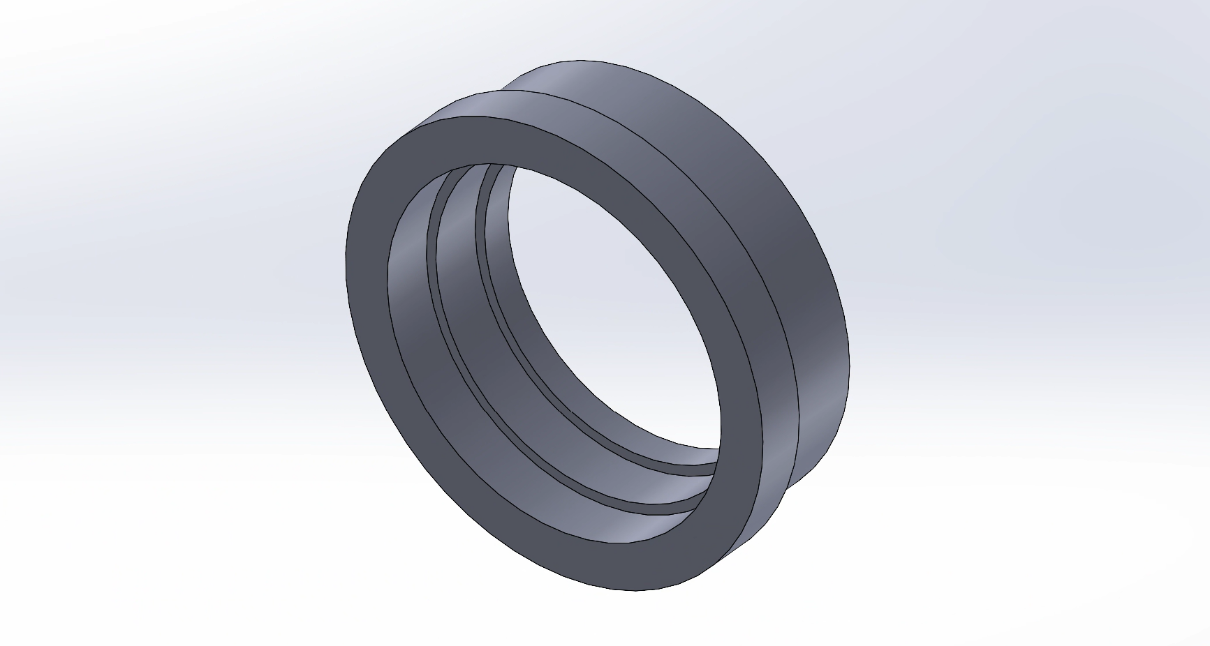
The image below shows most major features of this design: the extended skirt around the bottom of the holder (Step 1), the detailed lip on top (Step 3), the cut-out for our membrane device (Step 4), and the ventilation holes for gas exchange (Step 5 and 6).
Step 6: First Draft Design for Smaller Diameter Dish Holder
However, not shown in the image are the smaller chamfers and fillets that are added to the sides of the skirt piece and bottom of the holder to smooth out the 3D printed design. Furthermore, this is not the last iteration of this design, as it must be verified and tested to fit with the new petri dishes and the existing chassis. This process will be detailed with the following assignment: Homework 2: 3D Printing.


