October 22, 2023
For this fabrication assignment, we were tasked to create a small project using the Elgoo UNO R3 Super Starter Kit. After hearing about this assignment, I knew that this was going to be a more difficult process compared to the others. While we have been exposed to breadboards in our circuits class (BME10) and learned how to code in MatLab (ES2), we haven’t ever connected the two components before. As a result, I was most intimidated yet excited to do this assignment.
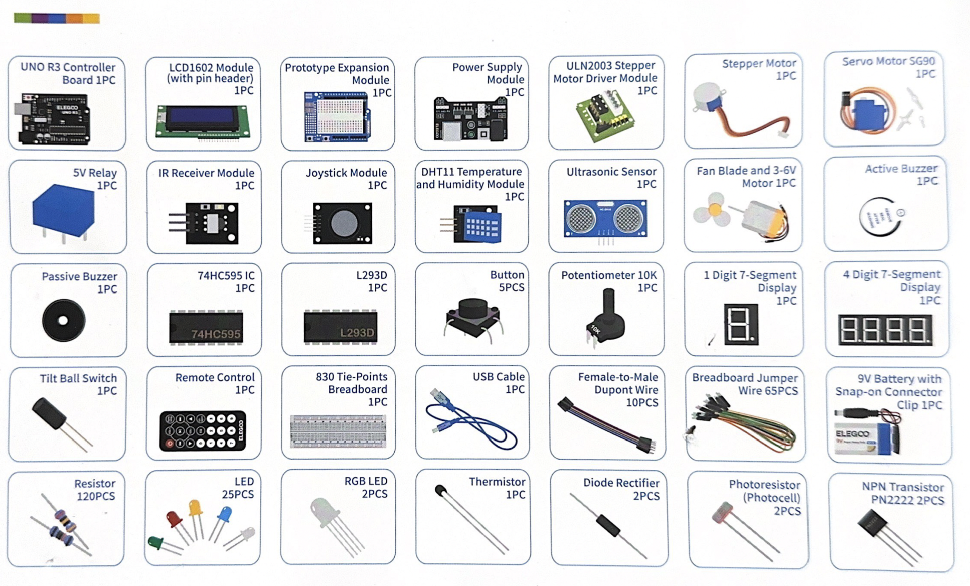
Since this assignment was pretty open-ended, I started by looking at the kit contents and the different modules I could play around with. At first, the fan blade with the 3-6V motor caught my eye as a more basic module to try before figuring out my final project. I followed a YouTube video online that walked me through the reasoning behind the wiring and also supplied the code. Unfortunately, the LED on the power supply module didn’t light when the battery was plugged in. That’s how I figured out my battery was dead. I wasn’t able to find a spare, and I did not feel like paying for a replacement battery from the Nolop shop, so I decided to try out some of the other modules.
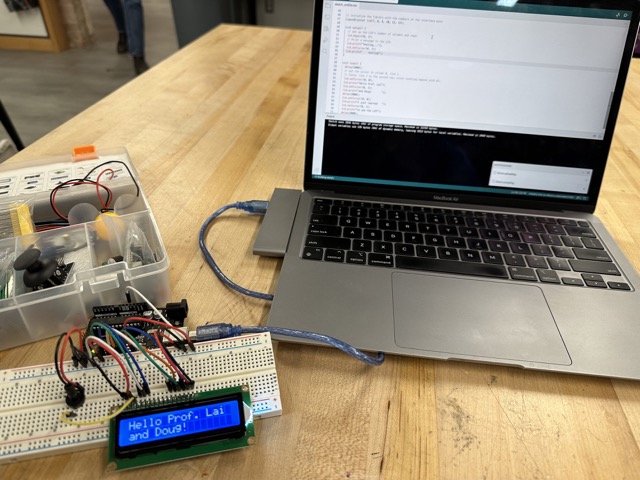
Since the fan didn’t quite work out, I chose to learn more about the LCD display next since I figured the output display code has similar logic to the Serial Monitoring section of the Arduino application. I decided to follow along with the LCD module video uploaded by the same YouTube creator. In the video, he shows his process of modifying the library code for running the LCD display (as well as his debugging process), so I became familiar with the coding format for the module. Luckily, the wiring formats were laid out in a neat manner that was easy to replicate. I was able to modify the display message and mess around with the spacing of the text. Additionally, by having the potentiometer, I could adjust the brightness of the LCD screen itself, which I thought was a cool way to visualize the effect of resistance on a module.
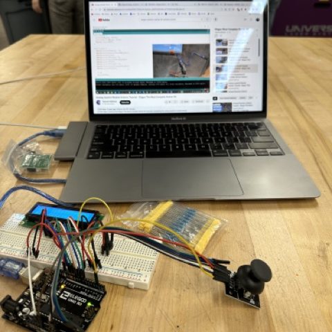
Now that I felt comfortable with the coding and familiar with the wiring of the LCD display, I wanted to move on and try a more difficult module: the joystick. I followed another YouTube video that explained how the joystick operates via the Y and X axes and a SW button and how to program actions based on the output values with their example code.
Using the joystick module taught me more about the analog in and outputs on the controller board. The joystick itself has X, Y, SW, 5V, and a Ground pin. The X and Y pins get connected to the “Analog In” side of the UNO R3, while the SW is connected to the “Digital” side, which will be important for the code later on.
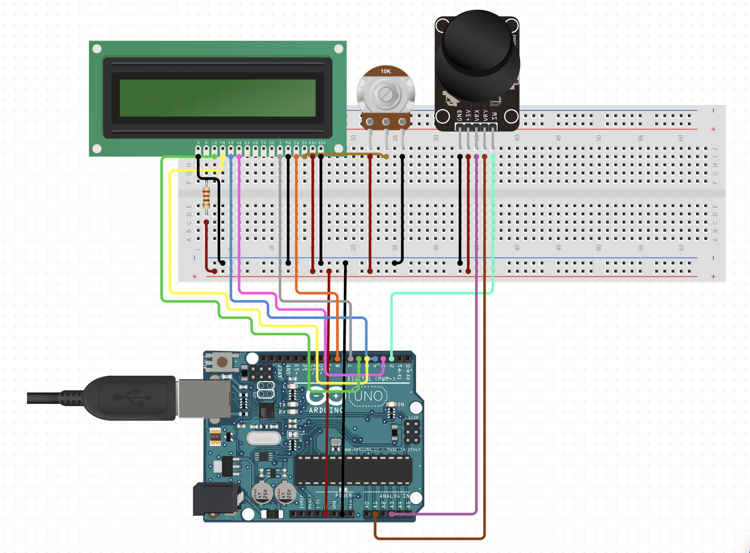
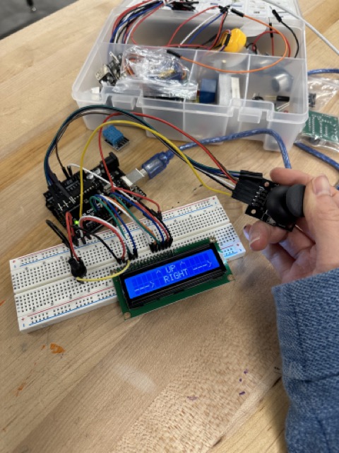
Next, it was time to start designing my small project. With the new skills of these modules, I decided that I wanted to combine the LCD and joystick by using the joystick and displaying the direction on the LCD display. Luckily, the input and output ports didn’t interfere, so wiring both modules together in one circuit wasn’t too difficult to do and pretty straightforward. When it came to coding, my inputs and outputs were connected to the same ports as before. Using the serial output values from learning the joystick module, I used the default X and Y values (neutral position) as the parameters for classifying when the joystick is in the left, right, up, or down position. After playing around with the values, I determined values that would prompt the LCD screen to display “Left” or “Right” on the bottom row of the LCD screen.
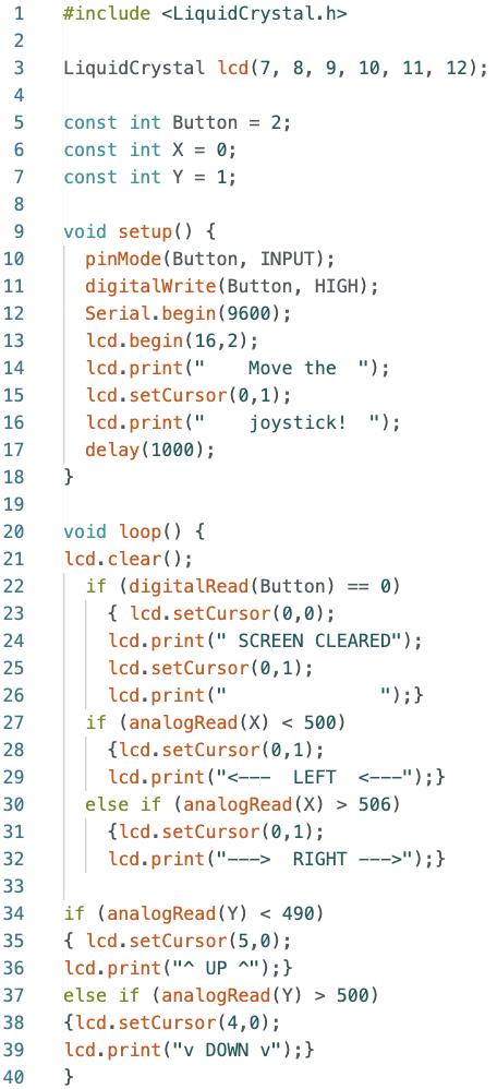
As I have learned from my MatLab coding experience, it is helpful to test code as you write it rather than debug all of your code at the very end. I started by programming the SW button (when you press the joystick) to clear the screen from any previous messages. I referred back to the sample code from following the YouTube tutorial earlier, added the same setup code, and used an if statement with “digitalRead(SW) == 0,” and so on. I didn’t have anything programmed besides that, so I moved on to coding the X-axis displays. The code did pass verification, but the LCD screen would only display “Left,” no matter how the joystick was oriented. After lots of debugging attempts, I realized I had written the line “digitalRead(X)<500” when the X pin is connected at an “Analog In” port rather than a “Digital Read” port. It took me an embarrassingly long amount of time to realize that I had to correct my code to “analogRead(X)<500” instead. Luckily, my code ran smoothly after this realization, and I was able to finish writing the rest of the code with minimal debugging needed.
Apart from the digital vs analog read realization and finishing the code itself, the second most time-consuming part of this project was perfecting the spacing on the LCD display. I found this LCD library of commands to be quite helpful. I included space bars in my print message so it would completely cover any previous messages. Otherwise, I would get displays such as “UPWN” where the “Up” and “Down” overlapped. Most of this was solved with a series of trials and errors with the spacing and uploading of the code.
I wanted to be able to display the direction when it wasn’t either left or right or up or down. Instead, I wanted to combine them so you could see if the joystick was down and to the left and so on, so I split the display by using the lcd.setCursor to the top row for the Y-axis and the bottom row for the X-axis.
Overall, I really enjoyed this fabrication assignment despite my intimidation towards it earlier. From playing with the microcontrollers, I learned more about how the specific ports affect the code with analog and display. I also enjoyed building a real-life example of a circuit diagram we would solve in our circuits class. I feel way more capable when it comes to building circuits and creating code to actually perform a task with a module. Another module I am eager to play with is the remote controller with the infrared sensor. I would like to see if I can use a microcontroller to turn on and off my lamp via a remote controller. My lamp has a pad that you tap to turn on and dim the light, so a simple circuit connected to a motor to rotate a fixed amount with every button press of the remote controller could control my lamp from my bed (rather than getting out of bed to turn off my lamp). With all of these fabrication assignments, I can find little ways to improve my daily life with engineered solutions. I can imagine my future house will be filled with 3D-printed objects with laser-cut decor and little microcontrollers.