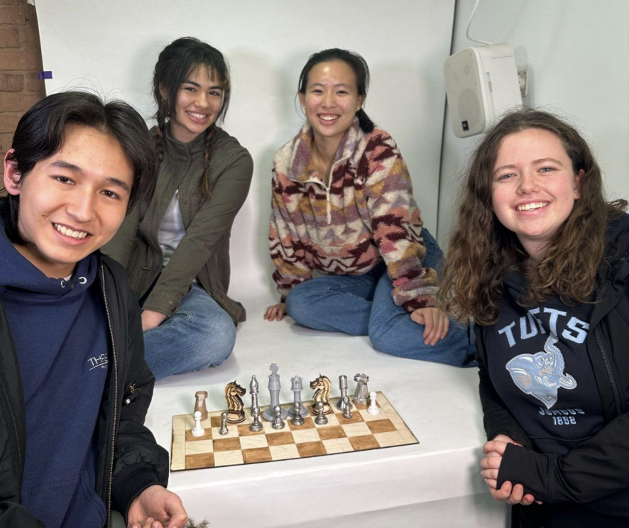
A Project by Natasha Wan, Julia Zelevinsky, Vivian Becker, Daniel Barszczak
GOAL:
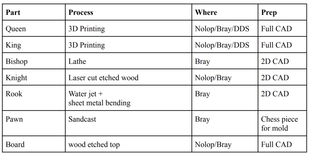
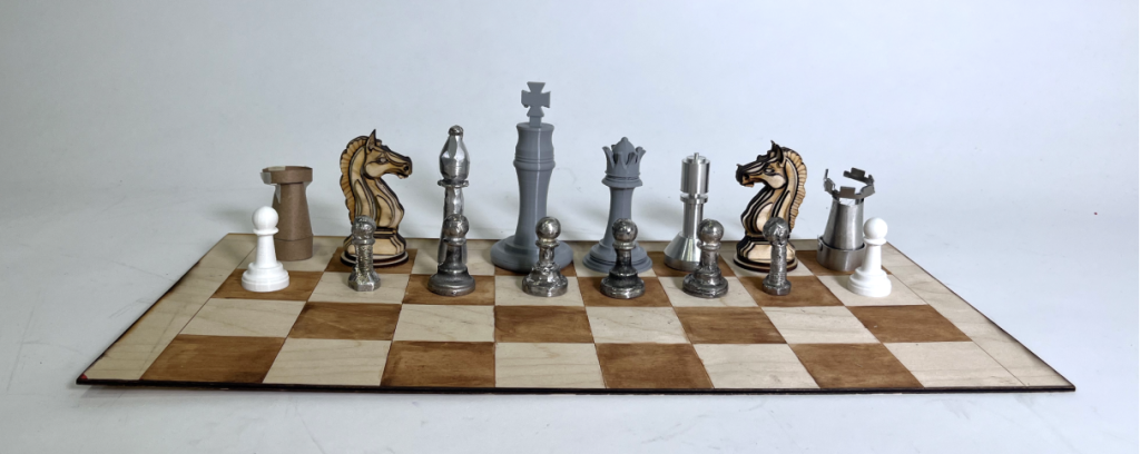
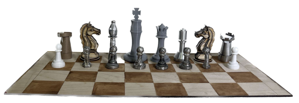
Our project reviews all the manufacturing techniques of the semester in the form of making a chess set. We wanted to optimize the advantages and disadvantages for the different fabrication techniques we’ve learned to decide which piece to make for each and ultimately be able to compare and document the processes.
WHAT WE DID & PLANNING:
Our final idea: A chess set! A chess set has a diverse range of shapes among the pieces. This presents a good opportunity to analyze the strengths and weaknesses of each fabrication technique, as well as gain experience. Additionally, the final product is a good way to showcase all of them in a cohesive way.
King and Queen
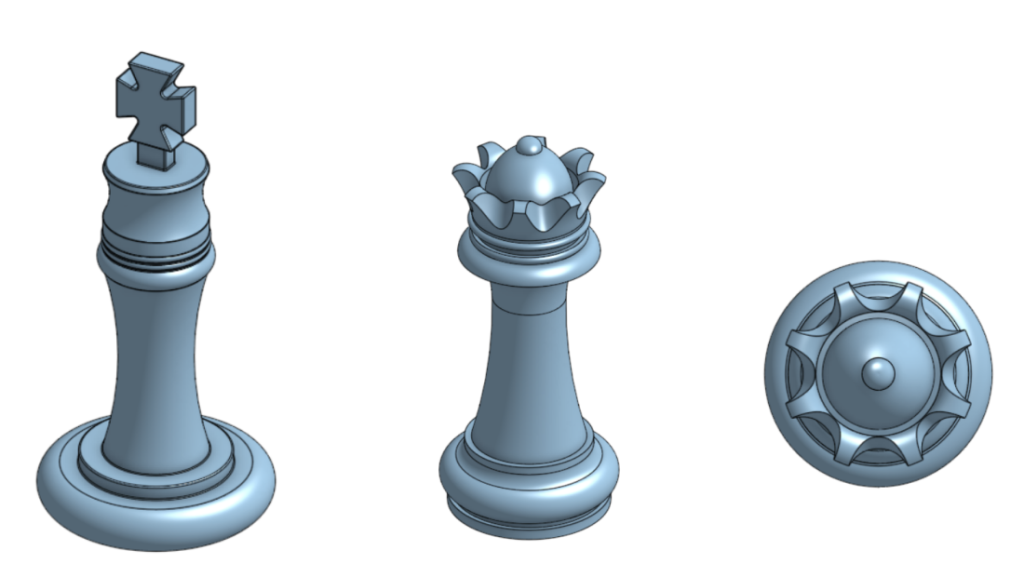
These pieces were 3D printing as they are quite complex and also the centerpieces of the board. We used OnShape to CAD the models and collaborate together. To determine the sizes, we tried to generally base it off the information here and we used a general size. Here’s what we designed:
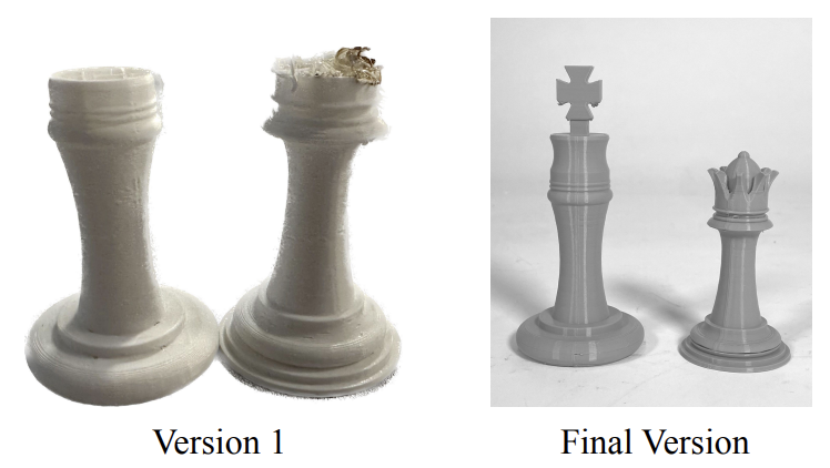
^ Our king and queen design that we created and then sliced to print. We used 10% infill and 0.2 mm layer thickness to try to speed up the process. Some of the challenges that we faced were that when printing in Nolop, the print kept failing:
We tried to reprint multiple times in Nolop but it kept failing, so we ended up switching to the Creality Ender printer in Bray, and it was successful! Our completed King and Queen are above.
Bishop
We decided to use the lathe to manufacture the bishop. We first started by finding a stock with the right diameter. We then proceed to file the stock into the right diameters to get the overall shape of the Bishop. One of the most interesting parts of the manufacturing process was using the lathe to make a tapered cut as seen on the base. It required moving to the tool post at an angle and then making the cuts. The challenging part was learning about how long it took to lathe as it requires mainly taking shallow passes to avoid machining it too much. Also the group member that had past experience lathing got COVID so we were unable to start the piece earlier. For our second bishop we basically went for a “manual lathing” approach by sanding down a stock piece of metal on the belt sander and using the soldering iron and soldering metal to add details to the shape.
Knight
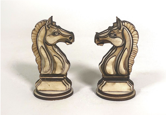
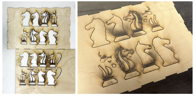
The knight is another more detailed piece in chess. For our knight, we created a 3D form through successive layers of laser cut birch wood to create a “topographical” map of a horse bust.
The biggest challenge with the laser cutting was that the smaller pieces fell through the bed of the laser cutter. To mitigate this we connected the small pieces of the mane into a longer piece and used etching for the “hair strands.” We learned that the etching barely showed up, and what we wanted was a “shallow cut” using a 0.001 in blue line. We also tried to carefully remove the pieces in danger of falling through with tweezers before removing the entire thing. Another issue was the charring and burning from the fire in the laser cutter. Some of the very thin, small pieces got so charred that they were difficult to use and turned out much smaller than expected. We learned that smaller pieces should be drawn a bit larger than needed. There was also some difficulty gluing the pieces together because some of the small/charred pieces did not have even surface area for the super glue to press together.
The difficulty of connecting separate pieces for both the knight and the second bishop taught us how much benefit you can get from producing pieces as one whole piece because the weak points of an object often occur where it has been connected
Rook
The processes chosen for this piece is water jet cutting, and sheet metal work (bending, riveting, shearing, etc…). This was chosen because it was a more simple shape that seemed pretty structural. Onshape was utilized to create the blueprint and aided in the engineering design and constructing process. To make the sheet metal CAD we had to make the solid part first and then we used OnShape’s sheet metal feature to turn the solid model into a sheet metal shape. The folded and unfolded models are shown below
Challenges that occurred first included bringing an idea to life as the CAD model did not necessarily show the connections between parts and also the processes needed to round out the metal. The 3-in-1 shear, bend and roller started the rounding process but further processes of hammering around a round object was needed to complete the final shape. The ending piece was not connected in the back as the rounding processes could not provide enough force to fully round the object. Another challenge was choosing the thickness of metal as, at first, a thicker (around .0765 inches) could not bend properly with the tools available. A thinner metal was chosen, however the small cuts in the crown of the rook lead to the first version snapping, and a hand bent crown was swapped in. Riveting was another challenge as pieces had a hard time lining up, with hole placement between three pieces causing a bit of a challenge.
Pawn
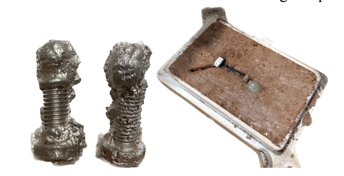
We decided to sand cast the pawns because we had to make a large amount of them and sand casting is a fast way to do that. When we started sand casting, we did not have a mold yet, so our first initial testing mold was a combination of a screw and a hot glue sphere.
Some challenges that we discovered through this test was that the pawn is radially symmetrical and not flat so we couldn’t simply remove it from one side of the sand cast to leave it negative space. Instead, we had to pack all the sand in first and then press the pawn into the sand. Then put the other frame on and fill in the rest. This way, the pawn is removable. Then, we switched over to using a real pawn lent to us by the Tufts Chess Club
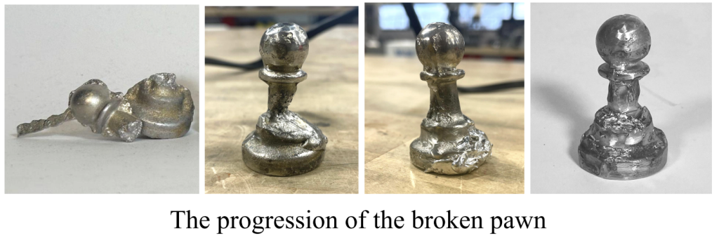
There were a lot of interesting defects that we experienced, including opening the cast too quickly, which potentially caused one to break and under filling of the molds (under shot).
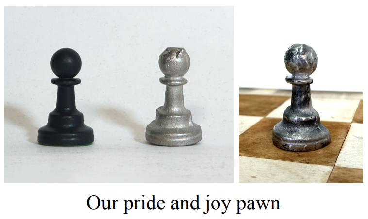
Since we had these issues and a lot of flashing, we then used the Belt Sander and the Polisher to make it so that the pawns could stand upright and remove the excess metal. We then also used a soldering iron to attach additional molten metal to the pawns that were not fully formed. This resulted in pawns that can all stand upright!
Since we made six out of metal, we then 3D printed two additional ones to complete out the entire set:
Board
We decided to laser cut the board because it is flat, made of wood, and made up of strict geometry. To draw out the squares, we used shallow cut instead of etching so it would be more visible. We then painted the “black” squares with brown paint for a wood stain look. The full board was too big to laser cut we decided to half it as we are only making half a set
Here’s a google drive link to a folder with our video documentation and additional photos: https://drive.google.com/drive/folders/1dI_xLcOItLtYu_2IGqaKJW22KacoeaDw?usp=sharing! We are planning to make a video out of them for ourselves later but wanted to include it here in case you were curious. We really enjoyed learning about all the different manufacturing techniques through this project.
