
Light Sensor using a Photoresistor (LDR)
When I was first exposed to Arduino, I thought it was the coolest thing and that I will finally be able to create/implement electrical components into designs and devices. Through this, I wanted to create an Arduino that could potentially be implemented into my team’s project. In my team’s project, we are trying to find a way to measure laser output in the form of absorbance depending on the skin tone/color of the vein and measure the difference between the two readings.
In this project, I am making an Arduino that measures the intensity of light using a photoresistor and LED lights to act as a visual indicator for each intensity level.

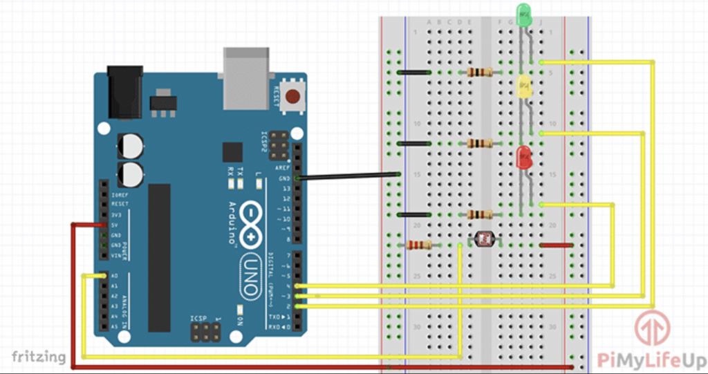
Using PiMyLifeUp I was able to gain the schematic for the breadboard and circuit layout in order to create the Light Sensor.
I used the following items to complete the Arduino :
- Arduino UNO R3
- Photo Resistor (aka a photocell that changes its resistance depending on the amount of light shone onto it, high intensity = low resistance)
- 4 x 220 ohm Resistors
- Red LED (indicator for high resistance or low/no light)
- Yellow LED (visual indicator for medium resistance or medium light)
- Green LED (visual indicator for low resistance or high amount of light)
- Breadboard
- Breadboard Wires
* Medium amount of light was measured by setting up a threshold in the code to be a value between the low and high values.


Looking at the schematic, they wanted me to connect one wire (orange) from the breadboard to the UNO R3, however, the wire wasn’t long enough so using the “Best Practice” schematic I tried to split up the wire to reach the UNO R3 better and easier. This was a “shot in the dust” because I didn’t know if the device was going to still work if I split it up this way.

After inserting the wire, I finished setting up the circuit I added all of the wires to complete the setup and I connected the UNO R3 to my computer and booted up Arduino.

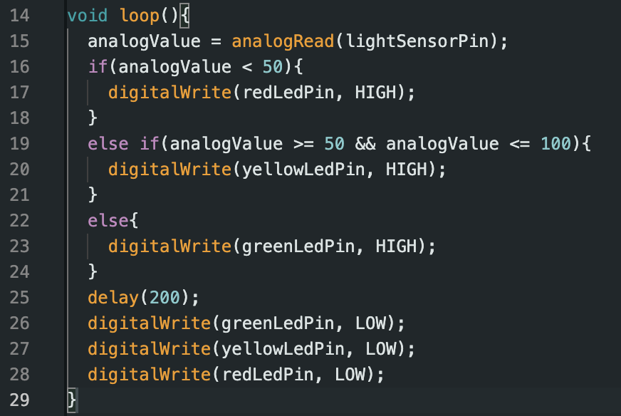
After creating the circuit board, I moved to Arduino to create the code needed to program the board to help it decide how and when to light up the green, yellow, and red LED light pins. I first set up all of the variables to store all of the pin numbers and the analog pin. Next, I had to declare the LED pins to act as OUTPUTs so it knows to have them light up depending on the amount of light. Lastly, the loop function is used by getting information from the analog pin (which is the photoresistor) and comparing the value to decide which of the three LED lights to light up. the Red LED will mean it’s dark out, the Yellow LED will mean it’s shady, and the Green LED will light up when there is light. After the loop, there is a delay of 200 ms, and turns all of the pins off, and check the conditions again.
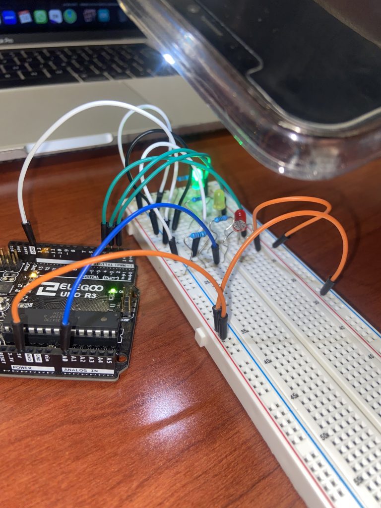


After completing the code and running it for any compiling errors, I tested out the sensor through three conditions : [1] shining a flashlight (phone) at the photoresistor [2] not shinning a light but having the room light on [3] covering the resistor with an item. These three conditions allowed me to see that the Arduino worked and that the right light was being lit up depending on the condition. This showed me that the Arduino worked and that it was measuring the amount of light normally.
MODIFY THE CODE TO HAVE IT SPIT OUT THE AMOUNT OF RESISTANCE
MAKE A SPREADSHEET ABOUT THESE VALUES
SEE HOW YOU CAN INCLUDE A LASER TO MEASURE COLOR/ABSORBANCE
Some things that were difficult to do was the wiring and making sure the wires didn’t get caught with each other since it would be hard to modify them later if any problems arose. Also making sure the LED lights were being placed in the right spot also confused me because I didn’t know which leg to put where but after looking it up more and referring to the slides, I was able to put them in the right spot.
I learned how to extend a connection using two small wires instead of one long one, the placement of the cathode/anode legs of an LED light, resistors for the sensors and lights, and use for-loops to compare data values that are being generated from a sensor.
Some potential uses for Arduino in my life are being able to create sensors that measure distance or velocity that can help get accurate and precise data for projects when compared to more traditional methods. Also being able to create motors for electrical wiring and compartments fin medical devices that require the use of a motor. Arduino can also be applied to the project being done in class since we not only want to measure the amount of absorbance but also find a way for both of the devices (the one with the laser and the photodetector) to move at the same time (parallel to each other) most likely using a motor.