
Summary of Major Design Changes
Since the last prototype, we have:
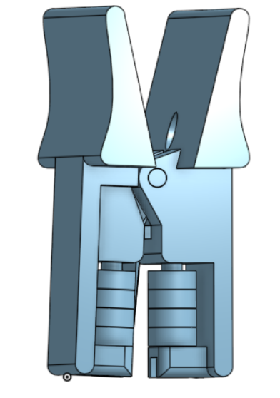
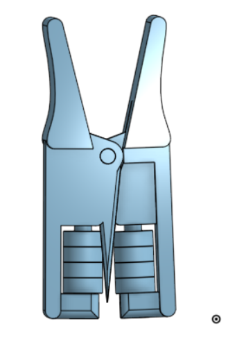
- Centered the closing mechanism apparatus (shoulder bolt and wheel bearings component) on the device
- Reinforced the body of the hinges and the pointed wedge with triangular shapes
- Also attempted to reinforce the pointed wedge by molding and casting it in another material
- Reinforced where the head of the shoulder bolt is secured on the device (by making sure the thickness was at least half the diameter of the hole)
- Rounded out the sides of handle for ergonomics
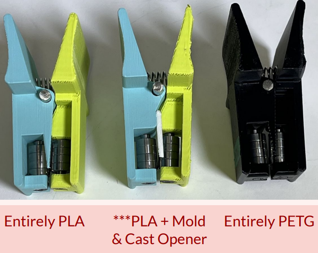
- 3D printed other iterations of the device using other materials
Throughout the course of the design process, we wanted to look into other ways to optimize our device. A few of them are documented below!
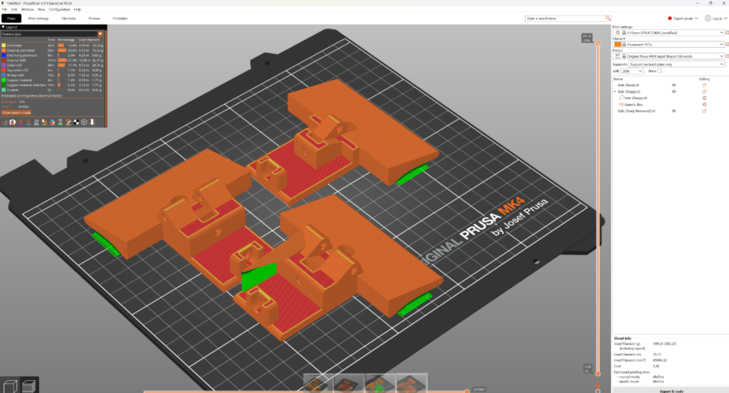
Printing Iterations with Other Materials
Originally, this started with a suggestion from Professor Lai to attempt to print our device using acrylonitrile butadiene styrene (ABS). Her reasoning for suggesting this was because ABS can use acetone as a solvent. Dipping our ABS prototype in acetone can cause the print to harden, allowing more fragile pieces (such as the wedge) to be reinforced.
After consulting with a 3D printing expert, we decided to take a different route. We decided to consult with Riley Patten, a research technician working in the Kaplan Lab. Although he said the department did not have any closed ABS printers that could maintain the appropriate temperature gradient needed for the print, he suggested printing with PETG and resin instead.
Polyethylene terephthalate glycol (PETG)
Riley assisted us with PETG printing. While PLA is more brittle (prone to snapping), PETG is less brittle but more ductile.
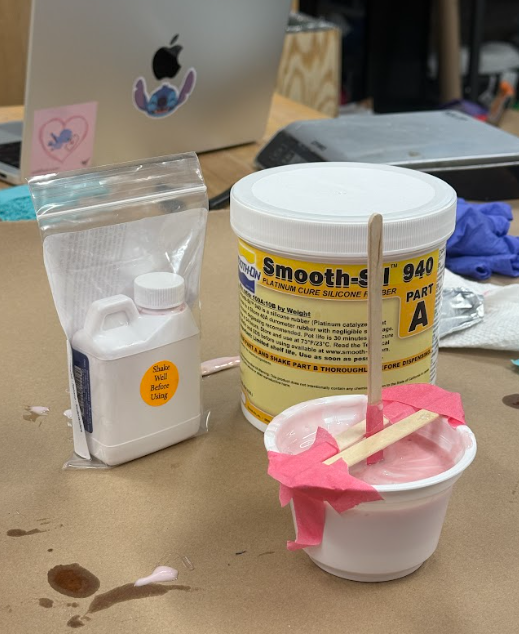
Molding & Casting the Wedge with Polyurethane
Because the wedge of our device was prone to snapping, we started looking into designing a detachable wedge that could be inserted into the body of our device through a threaded component. Professor Lai suggested buying threaded hardware that could be easily inserted into our device and printing the tip in another material, like polyurethane.
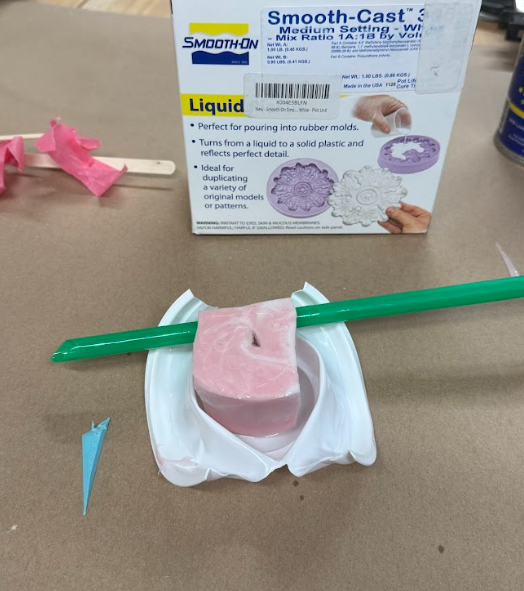
Zahir made a quick CAD file of our current wedge design. Then, Amanda and Maya 3D printed the wedge and used it to make a mold using Smooth-Sil 940. Since polyurethane is incompatible with PLA, we couldn’t directly print our mold.
After casting the wedge for the opening mechanism with polyurethane, we attached it to our device using superglue, as shown below. The white part is the polyurethane part!
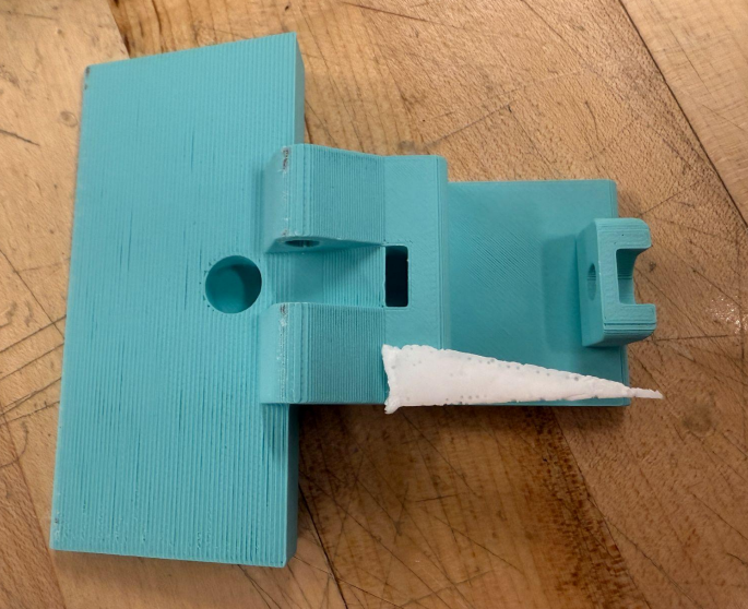
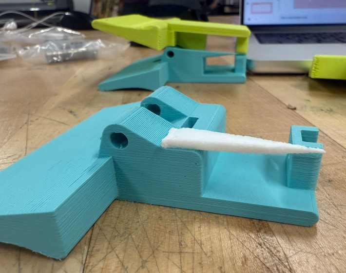
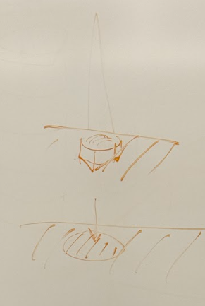
Regardless, if this were to use a molded and casted wedge on a final prototype (made out of a different material–not polyurethane), we would (ideally) not use glue to adhere the opening mechanism, since the compressive and shear forces would weaken the glued region. During our previous feedback meeting with Professor Lai, we discussed the idea of buying a removable threaded component, embedding it into the body of our device (as shown below). If we embedded a threaded part,
Next Steps / Future Considerations
Optimization of Materials
● Material diversity. We also wanted to consider SLA printing our device using resin or using ABS and hardening our device using acetone.
● Mold and casting. Since polyurethane was not as strong as we expected, we would like to look into other molding and casting materials for our opening mechanism.
Further Testing
● Stakeholder feedback. Ideally, we would have older arthritis users actively giving us feedback with every prototype iteration, but this was not possible given the amount of contacts we had access to for this project.
● Durability. We would like to look into more precise drop testing, as well as force-compression testing!
Scaling Up
● Mass-manufacturing. Ideally, we would not be able to mass produce our device (unless we had a 3D printer farm at our disposal). Solely relying on 3D printing would drastically limit our production time, compared to an industrialized molding and casting protocol.
● Ordering and shipping. Since we plan to ship our device in one piece (no user assembly), we would need to find a way to ensure the device does not break during transit.