Homework 2: CAD / SolidWorks
Assignment Overview
In this assignment, we were tasked with modeling an object of choice using Computer Aided Design (CAD). For this assignment, I chose to use SolidWorks! This was the only software package I used for this assignment.
Prior Experience Level
I would describe my 3D CAD experience as very novice-level. On the other hand, I have very extensive experience doing 2D CAD design. For my technical theatre scenery fabrication work, I have to produce a lot of “technical drawings.” Essentially, I would receive a “design draft” for the set of a play/musical, and my job would be to work out the logistics (budgeting/materials, assembly, dimensions) for constructing it! This ensures that there is a safe plan for executing the build before any carpentry and metal work starts.
In theatre, most scenic designers and technical directors use AutoCAD 2D software. AutoCAD is also the industry standard for many architectural design programs. For one of the shows where I was a scenic designer, I decided to mess around with the 3D elements of AutoCAD (since the set I was designing mostly comprised of simple geometric shapes like cubes, rectangular prisms, triangular prisms, cylinders, etc.). To see photos from that project, click here.
Outside of these simple shapes, I have had almost no experience in 3D CAD and absolutely no prior exposure to SolidWorks. Because our in-class CAD demonstrations used SolidWorks, I chose to use that program for this project to better familiarize myself to its UI and functions!
R2D2 Model
I decided to use the R2D2 modeling manuals given in class to learn the basics of SolidWorks. I started modeling the arm during the in-class demonstration, but kept working the rest of the parts (sporadically) outside of class. The process was confusing and frustrating!
Common Issues
One common issue I was having was that even though the manual had pictures, there were many points where I explicitly followed the text but noticed clear differences between what I had on screen and the photos. I had no clue what was missing or how to troubleshoot in many of these cases.
For example, when I had finished the base of the arm and was going to sketch the circle to create an extruded cut for the body, the manual said to toggle “flip the side of the cut” in order to make the cut point upward; however, when I did that, the software thought I was trying to extrude the area outside of the circle (rather than above the plane of the circle). On my initial attempt, I ended up cutting the arm at the part that was highlighted, but I managed to figure out the correct cut eventually!
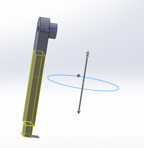
By the end of the first manual, I was relatively comfortable with making basic shapes in the software. I started trying to do one of the feet! I think the manual required a specific import, but since it was a box shape, I decided to model it myself with the sketch and extrude features. What I didn’t realize was that the box from the import was drawn “on face” with the front plane, rather than centered (like how I have it below).
This led me to the second most common issue I was experiencing: the thing I thought I was doing was clearly not what I was doing. When I had to extrude a cut for the joints, I had to deviate from the manual in order to get the cut I wanted.
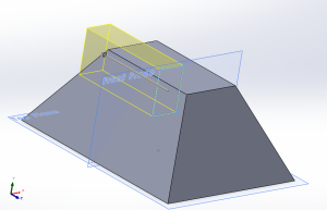
The fix was pretty simple. I just made the extruded cut go through both sides of the plane. There were instances where the fix was not as easy. I would select the wrong things, realize I made a mistake, and have to start over (especially during the beginning when I was making the arm in class). These hurdles made it a lot more satisfying when I finally got it correct!
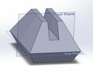
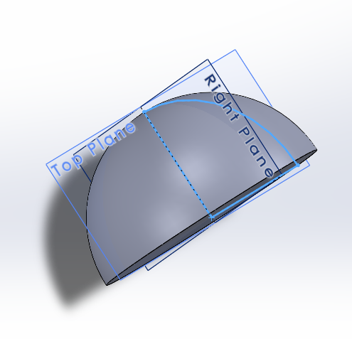
Some mistakes I made were honestly just silly. For instance, I still wasn’t used to having to manually select a plane before making a sketch. When I was modeling the dome for the head, I drew my sketch on the top plane rather than the top plane, which ended up giving me a dome that was in the wrong hemisphere.
Using the “Drawings” Feature (an unrelated side tangent!)
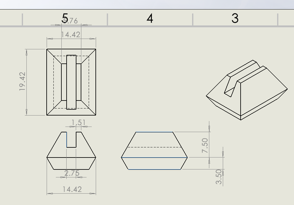
Even though our assignment was solely focused on 3D, I saw that 2D blueprinting was covered briefly in the manuals, so I wanted to test it out! I thought it was really cool that SolidWorks can auto-convert your 3D models to technical blueprints. Whenever I worked in AutoCAD 2D, I had to draw out every part (every piece of 2×4″, every sheet of plywood, lauan, etc.). This is so convenient!
(The only thing I have yet to figure out is how to move the drawings once I placed them.😬 I put my 4 drawings way too close to each other, and that made the dimensions on my drawing awkwardly spaced and hard to read.)
Returning to 3D — Learning Parts Assembly!
At this point, I had worked with the “part” feature and the “drawing” feature in SolidWorks. All I had left to do was follow the “assembly” manual. I created an assembly file and imported each of the R2D2 parts I made!
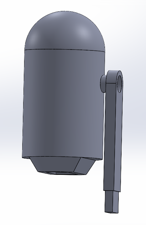
The process of aligning the parts together was relatively straightforward! I did, however, receive my first error messages when I mated the various parts.
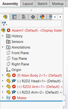
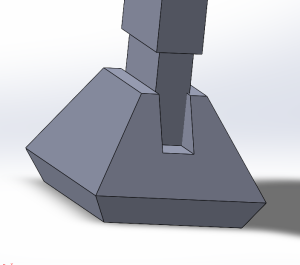
I could deduce where some of the error messages came from. One set of errors was because I tried to align both faces of the arms with both of the insides of the foot. The space in the feet where the arm is supposed to go was not the same width as the arm itself, meaning if I mated the two sets of faces at the same time, one of the mated pairs needed to be broken. This was an easy fix! I ended up just mating the outside faces so that the inside faces had a tiny overlap (shown below). As for the error messages that I got while trying to mate the arms to the cylindrical surface of the body, I have no clue why those persist.
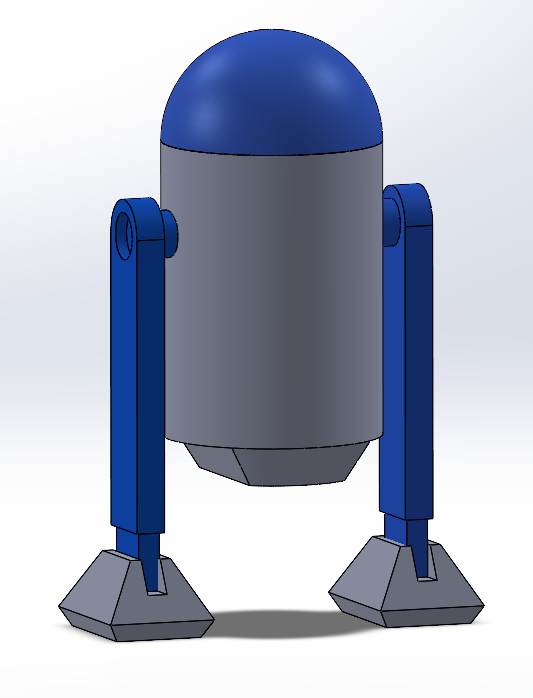
The final step in the manual was to add some colors to the model using the appearances feature! The result is pretty plain and nowhere as intricate as the official Star Wars design, but I was pretty relieved to have gotten through the beginner tutorial. I noticed that there was a “decal” option in the appearances module. If I had a .png file of R2D2’s texture, I could potentially go back in and wrap it around the body as a decal, if I wanted to.
What did I learn?
After this exercise, I was successfully able to:
- Navigate the SolidWorks interface and use various shortcuts
- Sketch various shapes using the Sketch feature
- Extrude various shapes to make 3D structures/parts
- Extrude cuts and make holes (circular & rectangular)
- Create a revolving extrusion about a rotational axis
- Use the Smart Dimension feature to set specific dimensions for my parts
- Set relative distances (“Relations”), either between different parts or a rotational axis
- Taper various edges of my parts using the Chamfer feature
- Create 2D blueprints of my parts through the Drawing mode
- Assemble individual parts and change their appearances in Assembly mode
Key Takeaways — Where do I go from here?
Although I would say that I have improved significantly from making cubes and rectangular prisms in AutoCAD, I still would like to try designing more objects with organic and irregular shapes. I’d also like to play around with colors, decals, and textures to make my designs look appealing/fun! In terms of time and efficiency, I still have a lot to improve on.
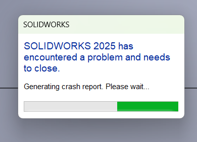
I also need to free up some memory on my laptop. Because I had Tufts TTS install the software directly on my PC, there were many times where my CPU fan was going haywire. I had some very fun error messages!
