Homework 3: 3D Printing
Assignment Overview
In this assignment, we were tasked to 3D print a free standing object. We were also tasked with trying to find various ways to optimize the print. Because I completely misread the instructions for this assignment, I decided to complete all 3 suggested optimization methods (minimizing material/print time, maximizing stability, and creating a hollow object).
For this assignment, I used an Original PRUSA M4 3D printer from the Nolop Makerspace in TTC. For my printing material, I chose to use PLA filament.
Prior Experience Level
I have had some 3D printing experience in the past, but it was just me printing off cool things I like or find useful off of Thingiverse. (Most of them have been tiny character models for Dungeons & Dragons campaigns!) When it comes to actually designing something with the intent to 3D print it, I am a complete beginner.
What to print..?
For this assignment, I decided that I wanted to model the object I was making in SolidWorks (either through following a tutorial or creating an original design), rather than printing a preexisting design. By doing this, I would also be considering optimization strategies in the CAD process as well as the 3D printing process.
I started by just brainstorming items. It was hard for me to think of an item that was hollow inside, so to get inspiration, I went on Thingiverse! I came across this really cute Power Star tree topper, based on the Super Mario franchise. The inside of it was hollow so that you could insert LED string lights inside of it before you put it on top of your Christmas tree!
I decided to look at the original creator’s .obj files to see how they chose to structure the 3D print. It seemed like they created two separate files (one for each face of the star) and ended up joining the two halves together by other means. I thought a star would be a really cool idea, but I was not sure how to go about making a hollow design with only one print at this point.
The CAD Process
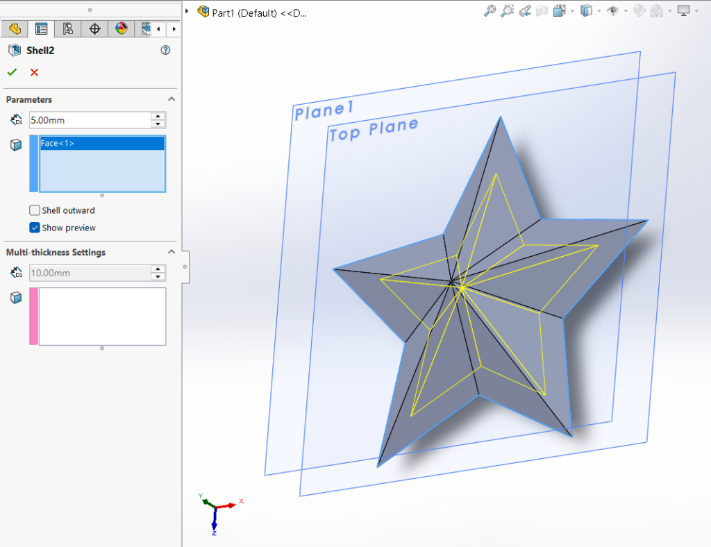
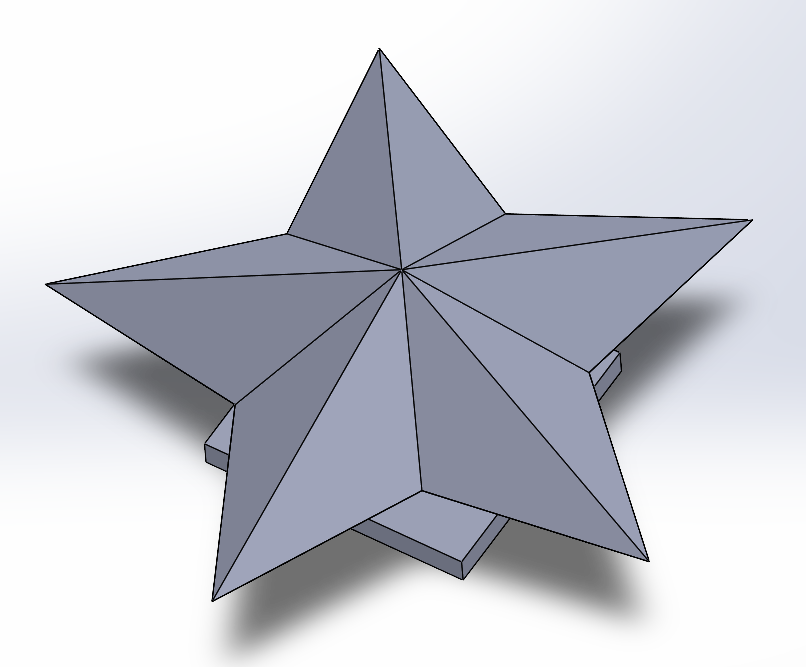
I started by just making a star. I followed this tutorial from Nayem Hossain to start off! Since the object had to fit within a 5″x5″ area, I decided to make my design roughly 100mm (around 4 inches), and scale all the measurements he used accordingly. After getting the solid shape of the star, I used the shell feature to hollow out the star shape so that the walls were around 5 mm thick.
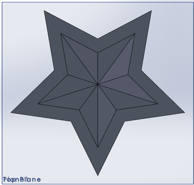
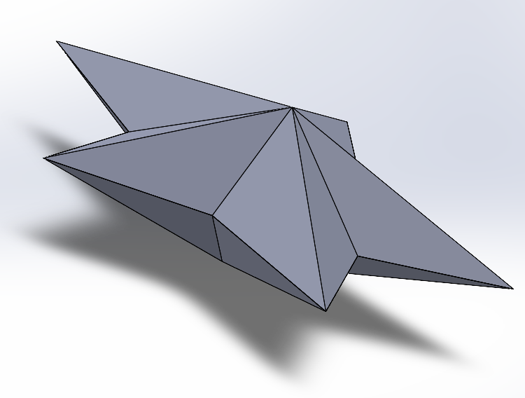
Once I had one face of the star modeled to my liking, I decided to create an assembly and join two copies of the same part. I really liked this design so far, but I was concerned about the technicalities what it meant to “maximize stability on a flat surface”, so I decided to give it a base. (I didn’t know if maximizing stability meant that the structure shouldn’t wobble or if it meant the object wouldn’t collapse if it was laid flat, so I chose to interpret it as the former.)
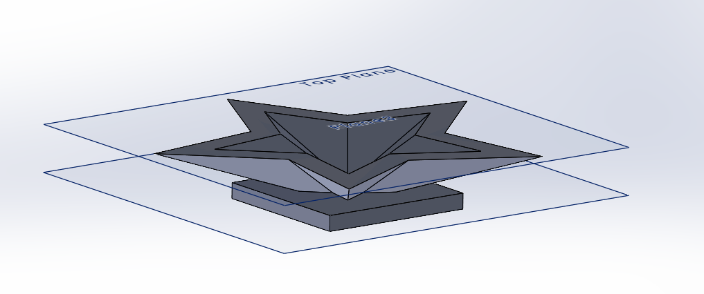
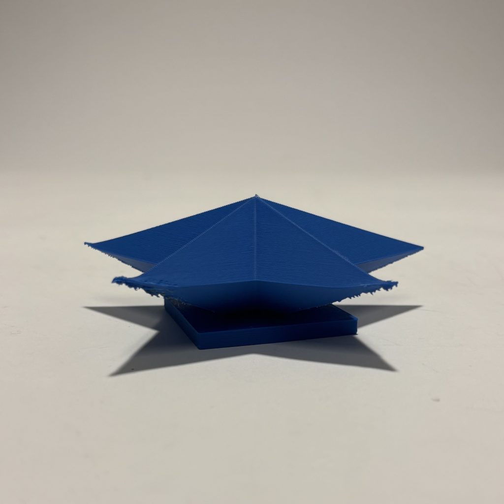
I went back in and optimized the stability. I duplicated my part, and added another plane 5 mm inward from the point of the star. Using that plane, I sketched a rectangle and extruded it so that the resulting base overlapped with the point of the star. I figured this would also give it my design more stability than if I were to just add the base directly to the point of the star. I rejoined the parts in assembly, saved my entire assembly as a part to merge the components, and converted my design to a .STL file.
The 3D Printing Process
Issues / Difficulties I Ran Into Immediately
At first, I tried splicing my .STL file using the splicer on the Nolop website. When I obtained the .gcode file and uploaded it to the 3D printer, I started the print. It did its usual calibration and nozzle cleaning, but for some reason, the nozzle cleaning failed. I didn’t know what to do at first, so I just cancelled and restarted the print job.
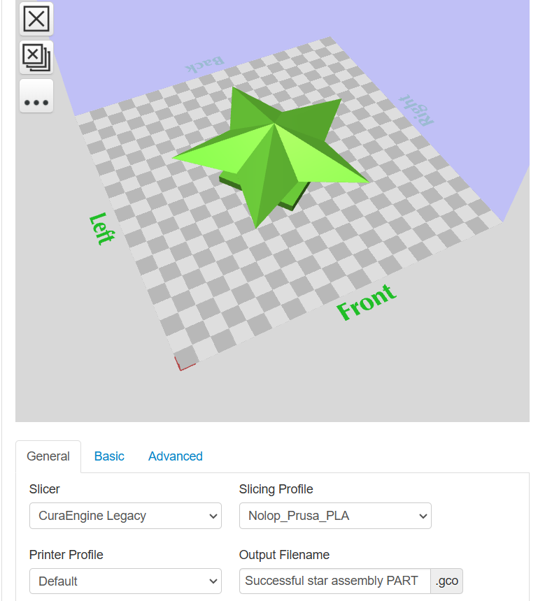
On my second print attempt, the printer successfully passed the calibration phase, however it was acting like it was printing when no filament was deposited from the hot end. I had a Nolop worker reset the printer for me and I tried again. (My theory was since I was using the same printer that Zahir just finished using, it was possible that the filament retracted itself into the nozzle when it cooled back to room temperature.) The nozzle started to print something eventually!
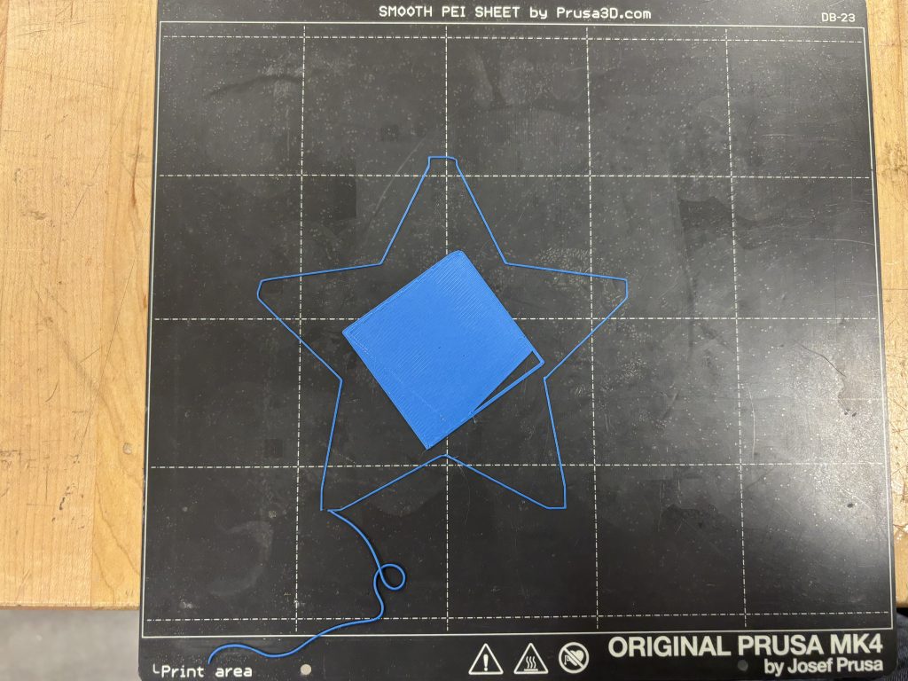
The Nolop worker that reset my printer thought the issue could’ve been caused by the gcode created by the splicer I used, since the 3D printer wasn’t listing an estimated print time (it was listed as “unknown”). (The “gcode”, either formatted as a .gcode or .bgcode file, is the set of instructions that the 3D printer uses to position the hot end in order to print a design.)
She encouraged me to resplice it using the desktop, rather than my personal computer. Because I didn’t want to risk using bad/inefficient gcode, I respliced my design.
Successfully Splicing the Design (More Optimization!)
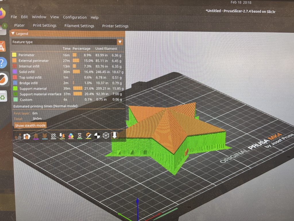
I imported my .STL file from a flash drive and onto the desktop at Nolop. The splicing program that I used was PrucaSlicer. With the guidance of one of the Nolop staff members, I first scrolled through the timeline of my print to check for any glaring issues that would affect the stability of the print. Next, I played around with the various settings to see if I could optimize the time of my print.
I first started by messing around with the infill density of the print. Infill density, as the name implies, is the amount of material that fills up the structure of a 3D print in hollow areas. As expected, when I decreased the infill density, the time decreased, and when I increased it, time increased. I decided to keep infill density at the default (15%).
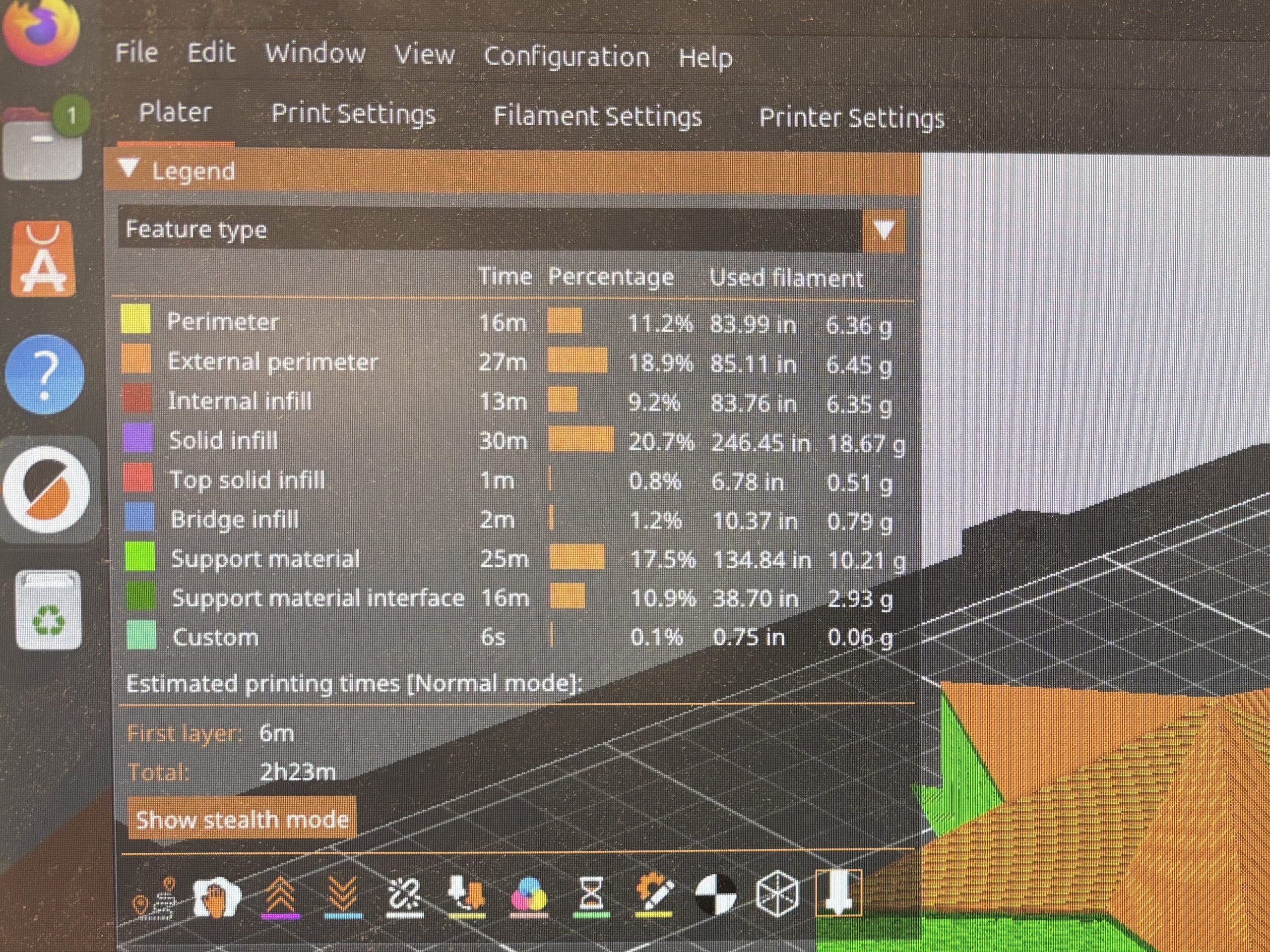
I also messed around with the amount of supports. I got mixed feedback on this from the Nolop staff! One person said that if you were unsure, you should add supports “Everywhere” as a safe choice. Another said to use “Supports on Build Plate Only” because it essentially did the same thing as “Everywhere” but with less time. When I started with “Everywhere” the print time was 3 hours even. When I switched it to “Supports on Build Plate Only”, the time went down to 2 hours and 23 minutes. Again, I looked through the print timelapses for each setting. Since both options still kept the integrity of my design (i.e., it kept the center of the star hollow), I opted for the shorter print time. It was a risk I was willing to take!
Playing the Waiting Game…
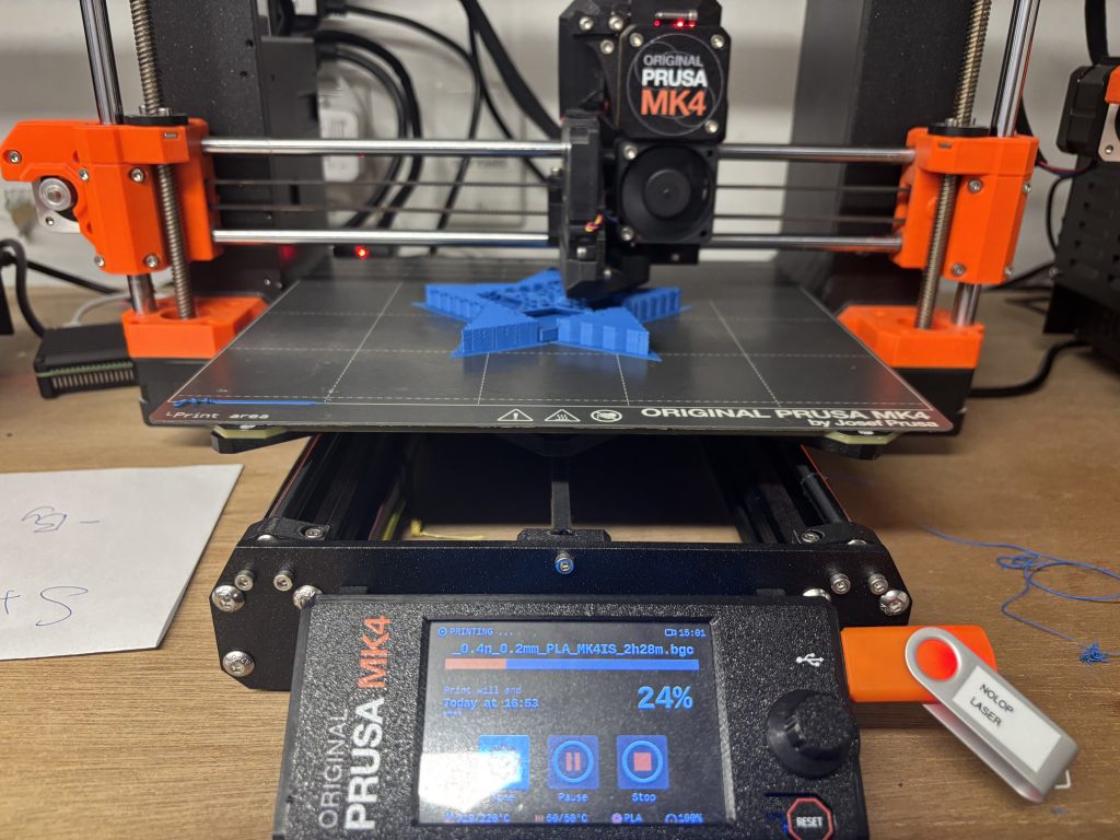
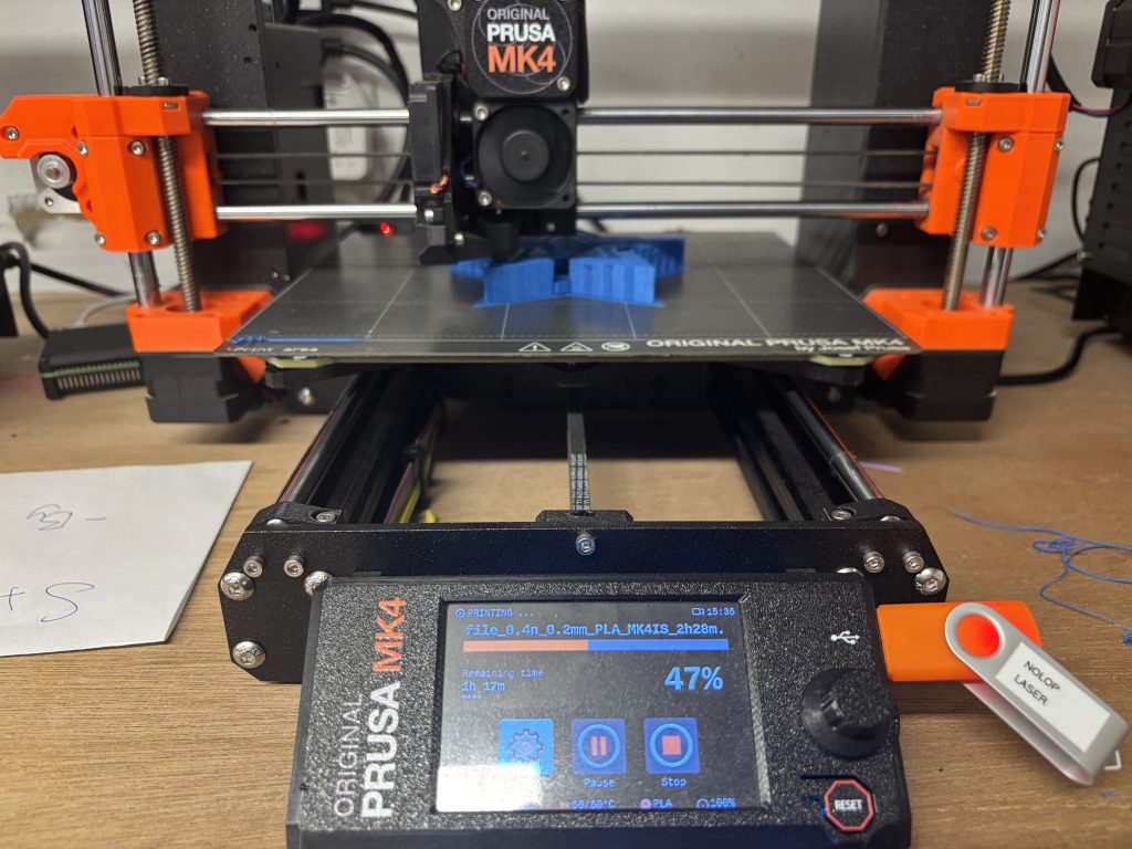
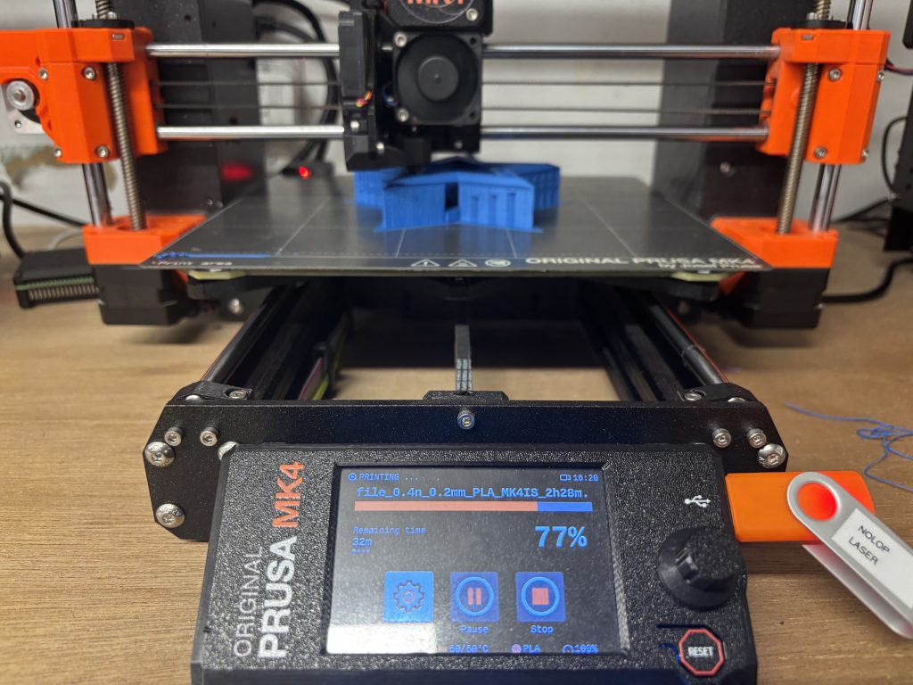
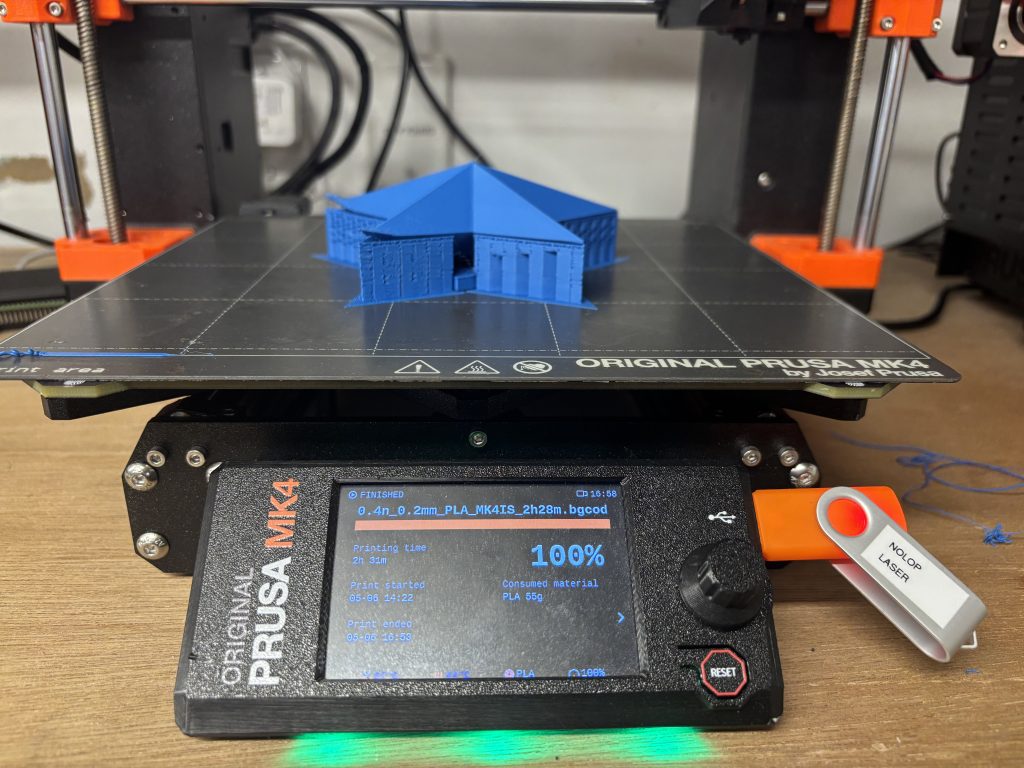
I waited for my design to print. I don’t know what to write about this part… so here’s some photos of the print after (roughly) each quarter of the print!
(I did choose to stay for the full 2 hours and 23 minutes, but I kept myself occupied with documentation for this assignment and proposal drafting.)
Conclusions
My total print time ended up being 2 hours and 31 minutes, and I used up 55 grams of PLA for my print. The amount of filament I used ended up being much more than I expected, however, I don’t 3D print things often so I wouldn’t really know how efficient this amount is in proportion to the size of the project.
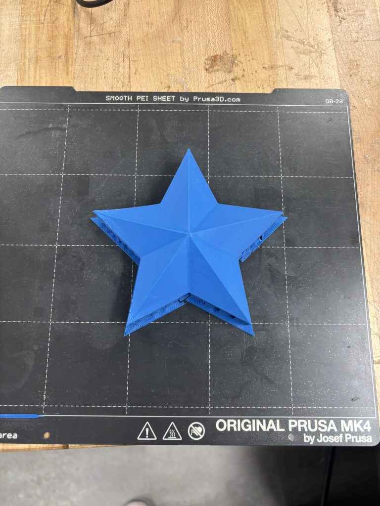
I definitely do think I could optimize this design a lot further! One of the things I was worried about was how fast the PLA would harden when cooled. It was one of the reasons why I made the shell depth so thick when hollowing out the star. Now that I have observed how the filament dries, I think I could’ve definitely pushed the thickness much smaller without worrying about the print collapsing. Alternatively, I could’ve kept the shell at 5 mm thick and decreased the infill density to around 7% or less.
The supports ended up being pretty thick (and very satisfying to break off at the end)! I wonder if the dry time of the filament would be fast enough for this design to be printed with no additional supports.
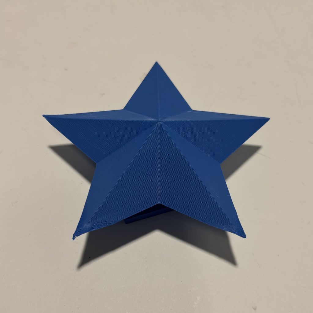
Overall, this was a very fun experience! I’m very grateful to the folks at Nolop for guiding me along the way. 😊
Using 3D Printing to Fabricate Traditionally Challenging Objects
When I think of cool 3D printing applications, my mind immediately jumps to biomedical applications!
In tissue engineering, scaffolds need to have the right mechanical properties to mimic the extracellular matrix. They are also often porous to maximize the surface area needed for seeding cells. Creating a biomaterial with both of these qualities can often be very difficult with traditional fabrication methods, but can be optimized via 3D printing! In this example, 3D printing can be used to create the scaffold structure, but some 3D printers are also able to print cells mixed with growth factors.
In BME 6 (Scientific Reading, Writing, and Presentations), my journal club group is currently analyzing a paper about in vivo 3D/volumetric printing for tissue repair! In Kuang 2023, the researchers use a “self-enhancing sono ink.” When this ink is 3D printed in high levels of penetration in a tissue, the researchers were able to use sonication frequencies are able to harden the ink, as apposed to traditional light curing methods. Traditional methods of tissue repair are often require extensive surgery, however, volumetric printing via injection into tissues offers an alternative therapy that can be minimally invasive.