For my first independent CAD Project, I decided to use SolidWorks on Tufts’ Engineering Lab to create a stamp/wax seal of my initials. The general CAD design for these two things are the same but the difference will occur in the materials they are printed with. For future reference, the wax seal would have to printed with a material that is super heat resilient given that it will be used on hot wax.
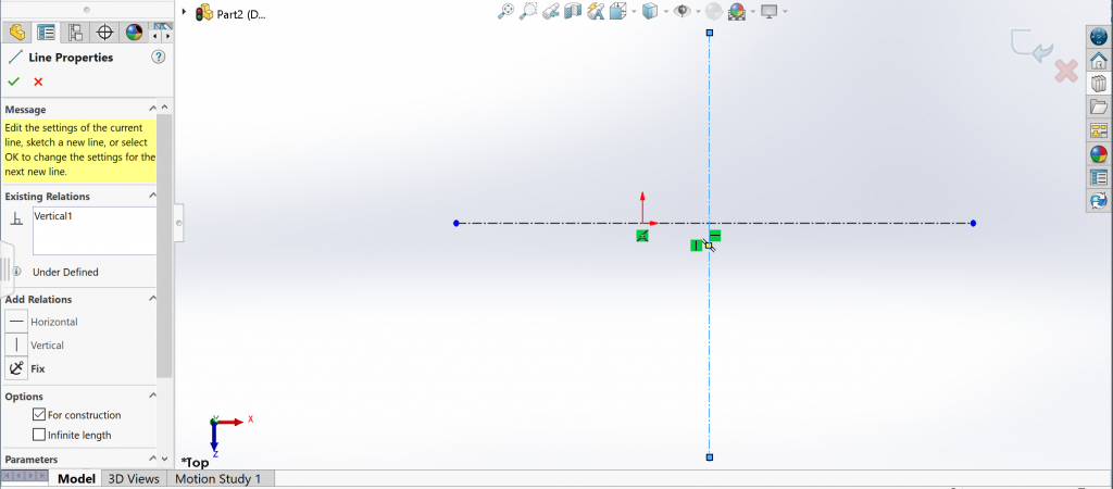
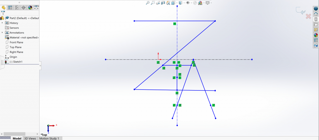
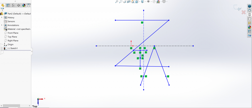
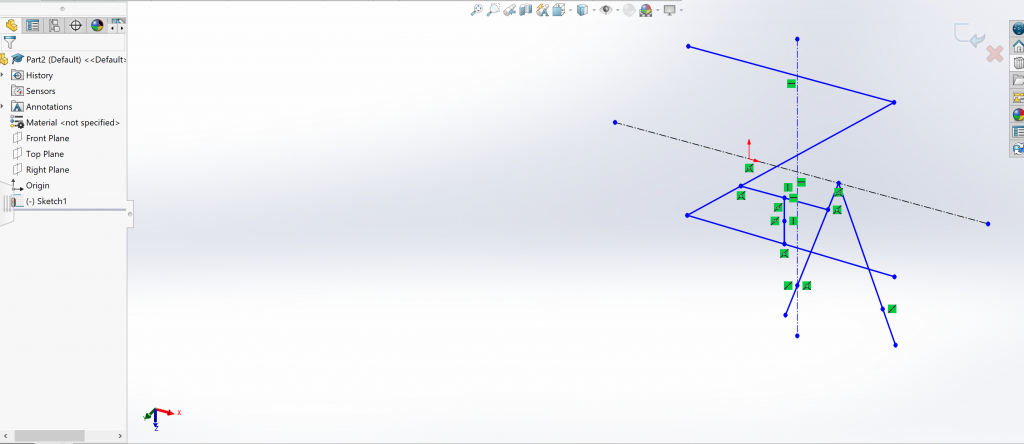
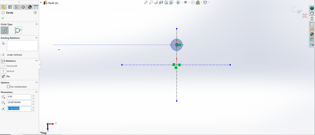
After changing my units to MMGS (ANSI standard) and also selecting the top plane, I was then able to create the centerlines for my project. To be completely honest, I didn’t really see much use for the centerlines when doing the original SolidWorks demo during class, but it proved to be useful, well at least in heavily geometrical designs, when trying to make sure the lines were straight.
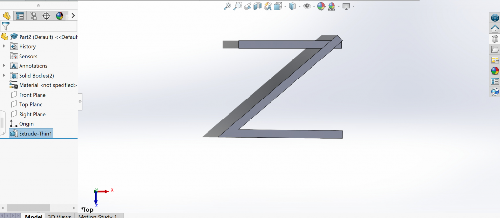
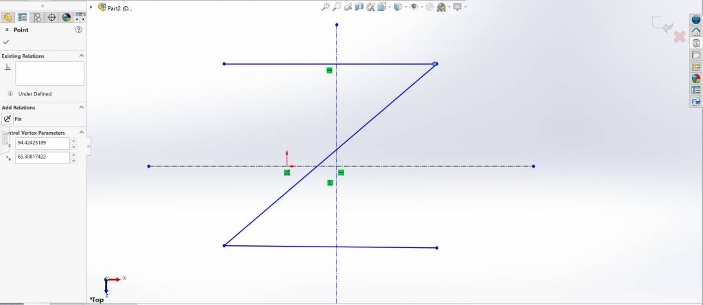
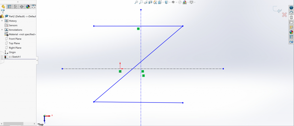
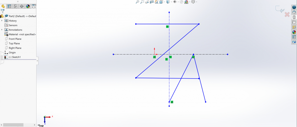
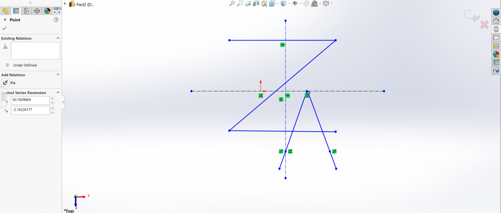
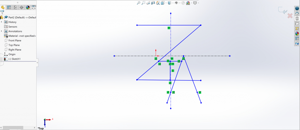
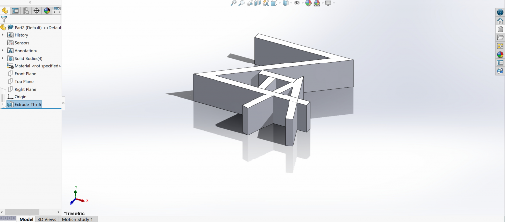
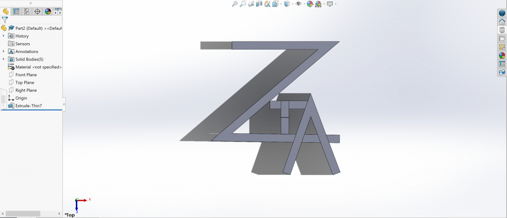
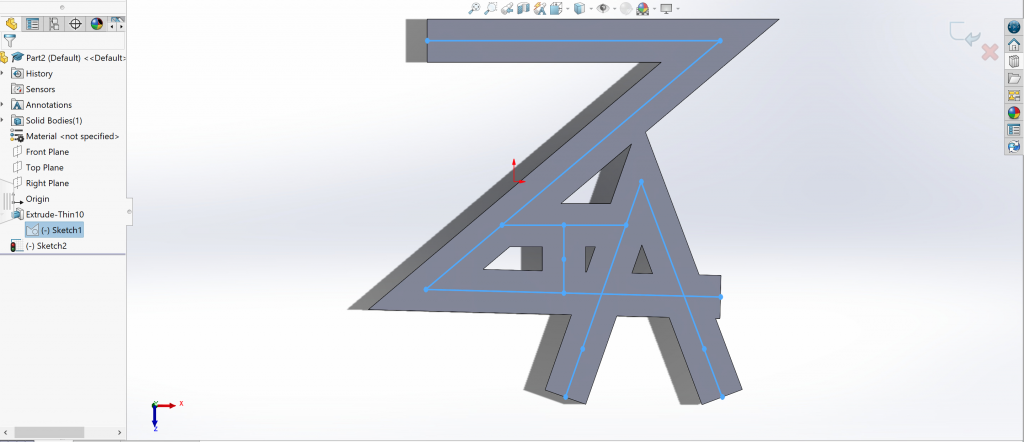
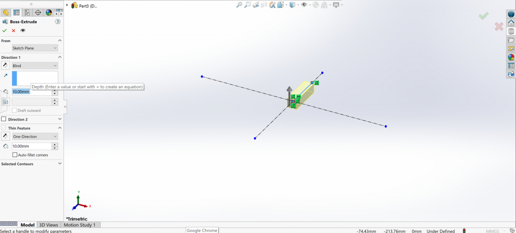
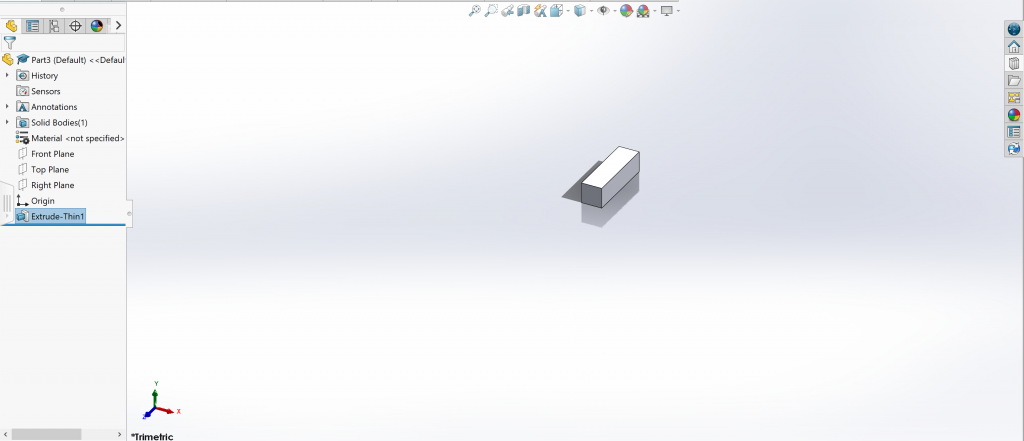
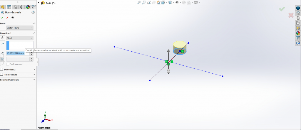
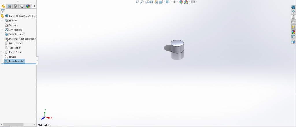
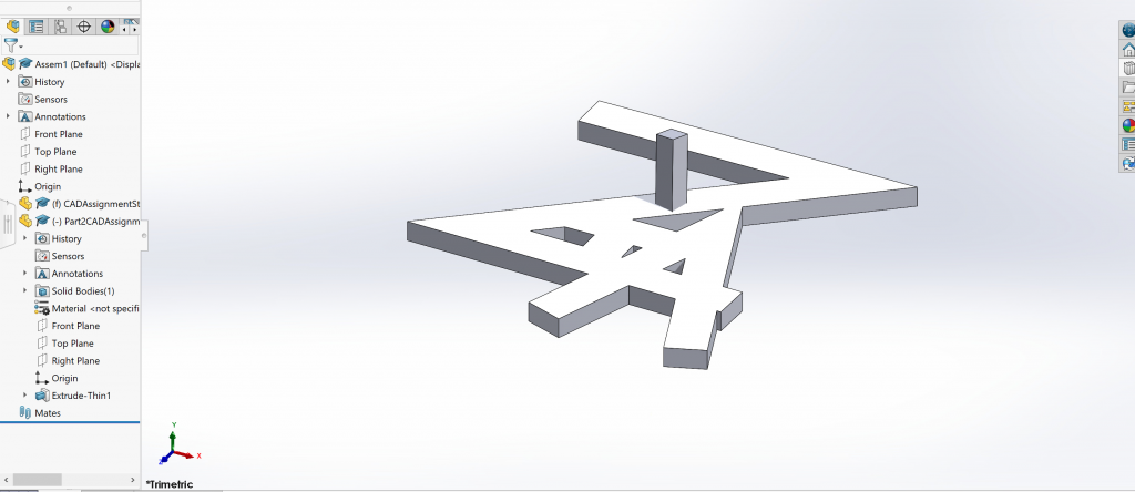
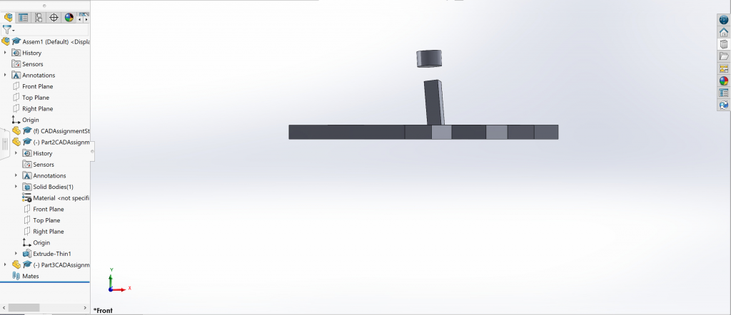
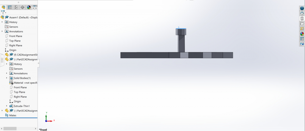
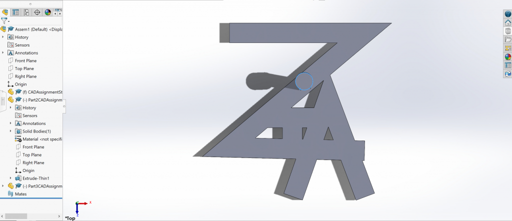
The first part of my design was to make the Z, given that it would be the largest element on the stamp. I created three lines and used the axis feature, the one that makes a dotted line appear when two or more things are aligned, to try to ensure that everything was the same length. In this first run through, my mistake was not connecting the slanted line with the top horizontal line. This mistake was made a few times throughout the entire design and it was the easiest to catch when the the element was extruded. The mistake in the Z that was extremely obvious when it was extruded can barely be seen in the top right corner because of the two overlaying circles indicating the end of the two unjoined lines.The mistake pointed out in the previous picture has been fixed and the top horizontal line and the slanted line are now joined.The fix can be confirmed by extruding the Z. The next task was to add the A to the original element. My goal was to make the entire stamp look cohesive so I decided to make the bottom horizontal line of the Z of my first name be the middle horizontal line for the A of my last name. This was the first run through of this design and I was able to noticed that the A look a bit unsymmetrical. The dotted line guide also helped me come to this realization. Here the A was corrected to be symmetrical.When the element was extruded, I was able to confirm that the A was symmetrical and also that both pieces were attached.The pictures above, show my 30 minute struggle with trying to make sure that my middle initial, I, was symmetrical. As seen above, I was struggling with centering the middle line for the I with the top line. I decided to use the bottom line of the Z as the bottom line for the I to make it look more continuous, but it was making it much harder. Also, I wasn’t sure if I wanted the top of the I to touch the edges of the A. In the end, I figured out that my mistake was changing the width of each line of the I, individually and not together. When I changed them together, they change of each line was proportional and I was able to tell if the it was symmetrical almost immediately. Another factor that helped was changing the axis of the design. This ended up being the final design for the stamp. One issue that I ran into when extruding all of the three elements combined was that it would only do one at a time. After clicking around a bit, I figured out that I could select all of them to be extruded at once. The next step was to create a new part for the stamp. This part, and the parts following, were the easiest because I just used basic shapes. The shape above was just an extruded line. The following step was to make a knob for the stamp as a new part. I decided to use a circle. The final step was to put all of the pieces together in an assembly. I started with the stamp design and then added the handle.This part proved to be the hardest for this step because from most angles, I couldn’t figure out how to orient the knob on top of the handle. As shown in the picture above, the knob kept disappearing into the design.After changing the orientation, I was able to see the how to better situate the knob on top of the handle and I was also able to see that the handle was extremely crooked. Some may argue that this way is more ergonomic, but for this design I wanted everything to be completely straight. I got frustrated really easily because I feel like the rotate option was very difficult to navigate on a trackpad instead of with a mouse.After what seemed like hours, the handle was straightened and the knob was connected. The design was finished on 2/12/23 and I hope to use this design in the next Fabrication Assignment, 3D printing. One thing I am worried about is that I assembled the parts incorrectly, but that will be a task for future assignments. In order to advance my knowledge in SolidWorks, I need to learn more about assembling individual parts together as well as finding more efficient ways to change the axis of the project.