Echocardiography Faculty Syllabus
By Dr. Suzanne Cunningham
Revised from original syllabus by Dr. Donald J. Brown
Objectives
- Develop an understanding of basic ultrasound principles.
- Become familiar with the indications and uses of echocardiography.
- Know the various echocardiographic modalities and what they are used for.
- Become familiar with basic echocardiographic views and echo characteristics of common cardiac diseases.
- Given a 2D or M-mode echocardiogram, be able to identify structures and phase of cardiac cycle.
I. Introduction
The combination of two dimensional (2-D) and Doppler echocardiography (“Doppler-echo“) allows for characterization of cardiac structure and function as well as providing important hemodynamic information. Echocardiography provides extensive supplemental data in the evaluation of cardiac diseases of animals and, in many cases, noninvasive diagnostic information obtained by Doppler-echo supplants the need for cardiac catheterization and angiocardiography, which are both expensive and time consuming by comparison. Doppler- echo does not however replace a carefulhistory, physical examination, thoracic radiography, or electrocardiography.
Although the discovery and use of ultrasound dates back to the early 1800s, it has only been used asa medical diagnostic tool since World War II. Since then, echocardiography has had a tremendousimpact in clinical cardiology and this has been especially true in veterinary medicine where thetechnique has been employed extensively only in the last decade. Its usefulness as a noninvasivediagnostic tool continues to increase; the recent advent of Doppler echocardiography has made itpossible to acquire clinical information (when combined with 2-D echocardiography) of a naturewhich is similar to that attained through cardiac catheterization. There are both advantages and disadvantages to echo techniques:
II. Advantages
Although sometimes employed during thoracic surgery (e.g., intracardiac echo or ICE) or via the esophagus (transesophageal echo or TEE), echocardiography is primarily a noninvasive techniqueand typically does not require anesthesia or sedation in veterinary practice.
Echocardiography provides anatomic information on the structure of the heart and great vesselsallowing examination of cardiac chamber dimensions, wall thicknesses, valves, chordae tendineae,etc. This fact also improves the specificity of echo studies relative to plain radiography orelectrocardiography, i.e. information derived from plain radiography is limited to various projectionsof the external silhouette of the heart and vascular structures. Motion of various cardiac structurescan be displayed as it happens (in “real time”) allowing the evaluation of various aspects of valvular and myocardial function.
III. Disadvantages
Techniques in echocardiography require significant skill, requiring years of training and practice tobecome good at performing the examination and interpreting the results. ECGs and radiographsrequire less skill by comparison. Although cardiac function can be evaluated qualitatively,quantitative characterization using echo alone is difficult. This is partly because no quantitative dataon loading conditions (preload, afterload) is obtained by echo alone. On the other hand, sufficientfunctional information can often be obtained to guide clinical diagnosis and therapy. Manyveterinary practices now have ultrasound equipment, and veterinary ultrasound use (for cardiologyand otherwise) is increasing dramatically and will likely continue to do so. It should be noted thatnormal pulmonary structures are not visualized and thoracic radiographs are still necessary inorder to make a diagnosis of heart failure (pulmonary venous distention, interstitial and alveolaredema, etc.) Thus echo does not displace the need for radiographic studies.
IV. Basics of Ultrasound
Medical diagnostic ultrasound is inaudible and ranges in frequency from about 1.0 to 10.0 MHz (megaHertz or million cycles per second). It is produced by applying an alternating voltage to a crystal whichexhibits the piezoelectric effect, that is a material which deforms in response to an applied voltage.Conversely, such materials also produce a voltage when deformed (as by reflected echos), and thisvoltage is proportional to the degree of the deformation. Because of this property, piezo crystals inthe transducer can be caused to emit ultrasound at a (relatively) fixed frequency, by applying asinusoidal voltage, and can also receive returning echos. The transducer spends the great majorityof its time in the “listening” mode, timing the arrival of echos. Actual transducers are often oblong inappearance, like a pencil, and we will sometimes describe the axis of the transducer according to thedirection in which it appears to point in space.
Fixed frequency ultrasound travels through soft tissue as a beam which can be directed at variousstructures by changing the angle and position of the transducer. The magnitude (loudness) of theultrasound is attenuated within the tissue by an amount which depends on the acousticalimpedance of the tissue. The impedance of air (and inflated lung tissue) is very great and no air canbe present between the transducer and the structures being examined. An acoustic coupling gelmust be applied at the transducer-body wall interface for this reason.
Whenever the beam encounters a change in impedance within the tissues, part of the beam is transmitted and part is reflected. Thus, when travelling through a homogeneous material (such asblood), very little ultrasound is reflected. The speed of ultrasound in soft tissue is fairly constant(1540 meters/ second). The distance to various structures in the path of the beam can be determinedby clocking the round trip time of a brief burst of ultrasound. The higher the ultrasound frequency,the more rapidly it is attenuated (i.e. over a shorter distance). At the same time, higher frequencyultrasound provides better resolution of cardiac structures since the waves being used to image theheart are actually smaller. It becomes necessary to trade off resolution for depth of penetration asthe size of the patient increases. For feline patients, a 7.5 to 12.0 MHz transducer might be usedwhile a 1.0 to 2.5 MHz transducer would be used for a horse.
Resolution is the ability of the device to distinguish between objects which are close to each other.The echo beam has finite width and tends to diverge as it travels through the body and this is a majorlimiting factor in lateral resolution. Depth (axial) resolution is determined, in part, by the wavelengthof the ultrasound; depth resolution is superior to lateral resolution.
V.”M-mode” (motion-mode) Echocardiography
M-mode echo is used extensively in both veterinary and human cardiology. This modality is used primarily to display valvular motion and cardiac chamber and wall thickness dimensions (y-axis)against time (x-axis) in a strip chart format. Gross anatomic defects can sometimes be appreciated, but the strengths of the M-mode exam lie in its ability to allow detection and quantification of hypertrophy patterns, to follow these patterns over time, and to facilitate assessment of rapidly moving structures (e.g. cardiac valves).
- Cardiac hypertrophy patterns:
- Pressure overload of the left ventricle (LV) or of the right ventricle (RV) results in concentric hypertrophy of the corresponding ventricle in which wall thickness is substantially increased relative to the chamber dimension. This is apparent as an increase in the relative wall thickness. Left ventricular pressure overload may be caused by subaortic stenosis (SAS) orsystemic hypertension; while right ventricular hypertrophy may be caused by pulmonic stenosis (PS), reverse patent ductus arteriosus (rPDA), tetralogy of Fallot (TF), heartworm disease, or other causes of pulmonary hypertension.
Volume overload of the left or right ventricle results in ventricular dilation, in which the cardiac chamber is increased relative to the wall thickness, and an increase in ejection volume,seen as increased or hyperdynamic motion of the walls of the heart. Causes of LV volume overload include mitral regurgitation (MR), ventricular septal defect (VSD), patent ductus arteriosus (PDA), or other arteriovenous fistulas, while RV volume overload may be caused by tricuspid regurgitation (TR), or atrial septal defect (ASD).
M-mode allows accurate measurements of wall thickness and chamber dimensions, primarily of the left ventricle, and can display abnormal wall or valve motion as well. Because ultrasound examination is localized to a small region of the heart, the M-mode display is able to depict rapidly changing events of the cardiac cycle and can be used to determine orestimate indices of cardiac performance such as the fractional shortening, ejection fraction, and systolic time intervals. Most other aspects of the ultrasound examination are bestperformed using two-dimensional and Doppler echocardiography.
Early use of M-mode did not allow simultaneous “visualization” of the heart in which anatomically meaningful structures could be observed. With experience, it became apparentthat certain structures of the heart exhibited characteristic motion or dimensional changes,making it possible to determine which part of the heart was being examined. Using this “blind”approach required considerable practice and experience to perform an examination. Withnewer technology, it became possible to visualize the anatomically meaningful display of the2D echo while performing the M-mode study, making examination by the latter considerably easier.
Standardized M-mode views result in characteristic appearances of certain structures. Examination typically is made with the transducer in the right parasternal position (RPS) at the4th to 5th right intercostal space such that right-sided structures are closest to the transducer(near the top of the display). The structures listed are not all visualized at once; thetransducer must be directed so that individual structures lie in the path of the ultrasound beam.
- Pressure overload of the left ventricle (LV) or of the right ventricle (RV) results in concentric hypertrophy of the corresponding ventricle in which wall thickness is substantially increased relative to the chamber dimension. This is apparent as an increase in the relative wall thickness. Left ventricular pressure overload may be caused by subaortic stenosis (SAS) orsystemic hypertension; while right ventricular hypertrophy may be caused by pulmonic stenosis (PS), reverse patent ductus arteriosus (rPDA), tetralogy of Fallot (TF), heartworm disease, or other causes of pulmonary hypertension.
- Right ventricular (RV) chamber dimension (Figures 1 and 2)—the internal chamber of the RV appears as an echo-free (i.e. black) zone near the top of the display. This region is sometimes obscured by “near field artifact”. For this reason, the RV free wall is often obscured in this standard view. The RV chamber dimension is normally much smaller than the LV dimension. As the RV chamber may be transected at variable angles and orientations when using the standard RPS position, M-mode interpretation of RV chamber size is difficult except in cases of marked enlargement.
- Tricuspid valve—often can be examined by M-mode, particularly in cases of RV enlargement. The two main leaflets, if both are visible, move in a fashion similar to the mitral valve.
- Interventricular septum (Figures 1 and 2)—the IVS is examined for its motion and its dimensions (thickness) in systole and diastole. Like the left ventricular free wall (LVW, see below), it normally thickens and moves away from the transducer (i.e. “down”) during systole as the internal dimension of the LV decreases.
- Left ventricular chamber (Figures 1 and 2)—is the echo-free space between the IVS and leftventricular free wall. The internal dimension (LVID) and relative change in dimension betweendiastole and systole (fractional shortening) are important parameters in assessing LV cardiacfunction clinically. The fractional shortening is defined as the change in internal dimension from diastole to systole, divided by the dimension in diastole: (LVIDd-LVIDs/LVIDd)
- Left ventricular free wall (Figures 1 and 2)—the LV free wall (LVW) thickness is also measured during systole and diastole and the motion is normally toward the transducer (i.e. ”up”) in systole.
- Mitral valve (Figure 3)—the two main leaflets of the left AV valve exhibit a characteristic motion and serve as an important landmark in “blind” M-mode studies. During diastole, the”anterior” leaflet (human terminology which persists in veterinary literature), which is closest tothe transducer, swings towards the IVS during the early rapid filling phase of the LV. The valvecloses part way during mid-diastole but reopens again at atrial contraction, due to the extraflow through the valve provided by “atrial kick,” before closing completely. The anteriorleaflet, therefore, inscribes an “M” on the tracing in the course of diastole due to motiontowards and away from the transducer. The “posterior” leaflet appears somewhat smaller andinscribes a mirror image of the anterior leaflet motion (i.e. a “W”), swinging away from thetransducer towards the LVW. S3 and S4 gallop sounds, if present, would essentially coincide intime with the first and second peaks of the mitral “M,” respectively.
- Aorta/aortic valve (Figures 2 and 4)—by angling the transducer up towards the heart base,the aorta and aortic valve are recognized by their characteristic motion. The near and far wallsof the aorta move essentially in unison as the heart moves in the thorax; the structure movestowards the transducer (i.e. “up”) during systole.
- Left atrium (Figures 2 and 4)—the left atrial appendage lies beneath the aorta, relative to thetransducer, and appears as an echo-free (i.e. black) space there. Though the left atrial to aorticratio (LA:Ao) is a commonly used measure of left atrial size, this index actually measures theleft atrial appendage (along with a hunk of periaortic fat….), rather than the body of the leftatrium and is not a particularly accurate measure of left atrial size, especially in the dog. Theleft atrial appendage is approximately equal in size to aorta in this view and the normal LA:Ao is< 1.3 to 1.
- Pericardium (Figures 1 and 2)—can be visualized as an echodense (i.e. white) tracing that liesadjacent (and just beneath) the epicardial surface of the LV free wall. If pericardial effusiondevelops, an echo-free space may appear between the two structures.
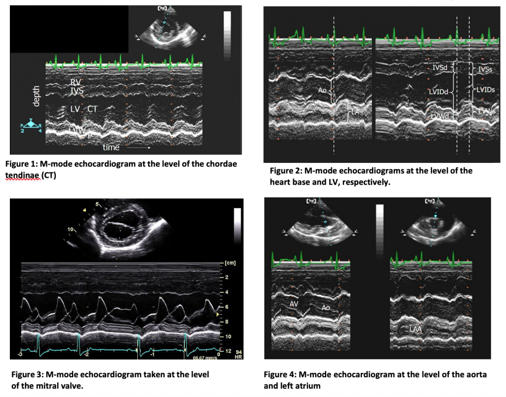
As discussed, the primary uses of M-mode are for mensuration of ventricular wall motion, thickness,and cardiac chamber dimensions. This information is extremely useful in a clinical setting for thediagnosis of conditions which cause changes in these parameters due to “appropriate” hypertrophy(from diseases which cause volume or pressure overload) or “inappropriate” hypertrophy patterns(such as cardiomyopathy). Measured values are compared to established values for a given species andbody weight to aid clinical judgements. Functional information is gained by observing wall motion andcalculating performance indices, such as the fractional shortening. These must be interpreted withcare since they are dependent on loading conditions (i.e. cardiac preload and afterload). Valves maybe observed for thickening and/or abnormal motion such as might be caused by degenerative orinfectious processes. Other structures can be “visualized” by M-mode (pulmonic valve, right atrium) butmay be more difficult to correctly identify and/or evaluate. Also seen may be papillary muscles,chordae tendineae, heartworms, and tumors.
VI. Two-dimensional (2D) Echocardiography
Two-dimensional echocardiography displays a tomographic image (slice) of the heart in real time and allows the clinician to visualize anatomic defects of the heart in many cases. Theappearance of the display is anatomically meaningful and structural relationships within the heartmay be discerned. Nevertheless, the display represents a two-dimensional “slice” through theheart and structures not lying in the plane of the slice cannot be seen without repositioning thetransducer. An incomplete list of potential visualized diagnoses includes VSD, ASD, PDA, valvularthickening or dysplasia of any of the heart valves, abnormalities of the mitral or tricuspid apparatus, cardiac tumors, or heartworms. The experienced echocardiographer can usually discern hypertrophy patterns, as described above for M- mode exams, by visual inspection of the real-time 2D images. In addition, because of the complexities of cardiac anatomy and spatial orientations, 2D allows superior evaluation of the right ventricle and both atria as compared with standard M-mode methods. Quantitative data can be derived by measuring distances or areas from images.
An echocontrast study is a simple and useful supplement to the standard 2D technique, for cases in which an intracardiac shunt is suspected. This is accomplished by the injection of an echogenic solution, usually into a peripheral vein, with concurrent 2D or M-mode recordings. Aeratedcontrast agents such as indocyanine green have been employed for this purpose, but agitatedsaline seems to work just as well. Microbubbles are highly echogenic and are completelyremoved in the pulmonary circulation so that any contrast appearing in the left heart indicates a shunt at the atrial or ventricular level. A right to left (R to L) shunt results in contrast in the LA (Rto L ASD) or LV (R to L VSD). In left to right shunts, the right- sided pressure may still exceed theleft during some portion of the cardiac cycle (e.g. early systole) and contrast may still appear onthe left, confirming a shunt diagnosis.
The production of 2D echo images:
Mechanical sector scan – With this device, the piezo crystal actually rotates or oscillates back andforth on a wheel inside the transducer. The crystal emits a burst of ultrasound in a given direction,receives the returning echos and displays them as a function of depth and strength (brightness),then changes angle slightly within the scan plane. The process is repeated until a scan is completeand a single frame image is formed. Individual video frames or images are then displayed in rapidsuccession to give the appearance of cardiac motion.
Phased array sector scan – this newer technology employs multiple piezo crystals which are precisely placed within the transducer; each crystal produces an ultrasound wavelet. By preciselycontrolling the firing time of each crystal, the wavelets combine to form a wave which takes on aspecific direction into the tissue. Repeating this process, but with rapidly changing wave angles, results in the image scan as before.
The M-mode echo can be produced with either of these transducers by selecting a particular beamdirection, and displaying the image against time. Some of the standard views for the 2D echo arealso performed from the RPS position (others not discussed today). From the RPS position, thereare several different standard views of the heart, but only two basic kinds of views; short axis and long axis.
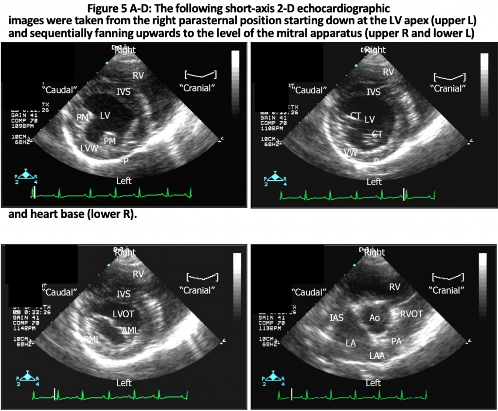
- Short axis views (refer to images below) – In these views, the 2D scan plane slices the hearttransversely, or in “cross-section” (as opposed to lengthwise in long axis views). In terms of alateral radiograph, the short axis views slice the heart roughly perpendicular to the ribs. Variousshort axis views are then obtained by angling the transducer towards the base or apex of theheart. As you read through the description of the 2D echo anatomy, imagine you are holding agross specimen and can visualize the full, three-dimensional structure of the heart. Remember from radiographic anatomy which structures lie cranial or caudal, and which are near the apex or base. Sequential views will be described below from apex to base.
- Apex—The left ventricle appears as a donut-like structure with the central echo-free zonecorresponding to the internal chamber. The RV internal chamber may not be visible, ormay appear as a crescent shaped echo-free zone in the near field. It may be obscured by near-field artifact.
- Level of papillary muscles—Similar to previous view but the diameters of the LV and RVincrease size in the baseward direction and internal bulges of the “anterior” and “posterior” papillary muscles of the LV appear at the endocardial side of the LV free wall.The optimal orientation of the M-mode echo beam, for assessment of ventriculardimensions and function, would occur in this view by selecting the beam angle whichextends from the transducer (top of the sector), through the center of the LV chamber, andtransecting between the two papillary muscles. This cannot always be accomplished.
- Level of chordae tendinae—With further angulation towards the base, echodense chordae tendineae appear in place of the papillary muscles as they course baseward tothe mitral leaflets. The RV continues to enlarge, retaining its crescent-like, thin- walled appearance.
- Level of mitral valve—The anterior and posterior mitral valve leaflets appear with theircharacteristic double opening motion during diastole. The orifice has an ellipsoidal, “fishmouth” appearance. The anterior leaflet moves towards the septum upon opening whilethe posterior leaflet moves towards the LV free wall. RV papillary muscles may be seen tobulge from the septum on the RV endocardial side, or appear to float in the RV chamber(these are sometimes mistaken for “masses” in the RV!).
- Base—The short axis view of the heart base is somewhat complex since many structuresare visualized; locations of structures will be described in terms of a clock face with thecross section of the aorta at the center (refer to the lower right image below)The leftatrium (6 to 8 o’clock) appears at the previous location of the mitral valve (since it actuallylies directly over the valve); the left atrial appendage (LAA) (4 to 6 o’clock) curves aroundthe far (from transducer) side of the circular aortic cross section which appears at thecenter of the image. The right ventricular outflow tract (RVOT) (1 to 4 o’clock) curvesaround the opposite (near) side of the aorta and can be followed to the pulmonary valveand out into the main pulmonary artery (with more baseward angulation). All three cuspsof the aortic valve can often be appreciated giving a characteristic three spoke wheel (or“Mercedes-Benz sign”) appearance; the spokes correspond to the commissures of thevalve. The main leaflets of the tricuspid valve can be seen (10 to 12 o’clock) whichseparate the RV from the RA (8 to 10 o’clock). Exact locations of the structures vary withbreed and species conformation, and with transducer orientation (can completely reverse left to right by rotating the transducer 180 degrees).
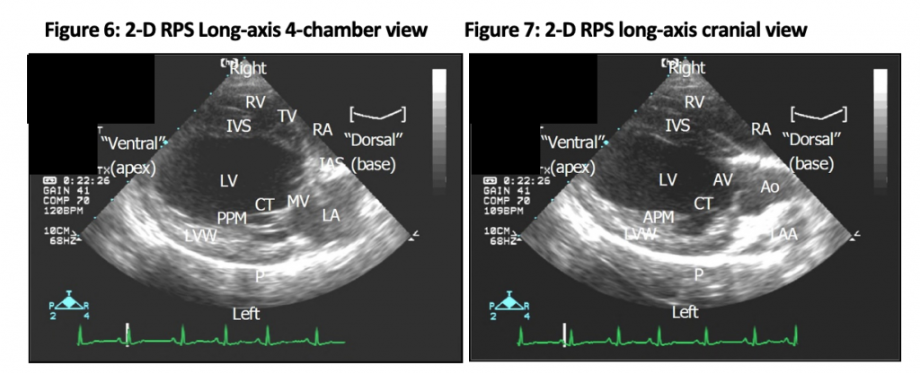
- Long-axis views – are obtained by rotating the transducer clockwise 90° about its axis, fromthe short axis view, so that the scan plane slices the heart lengthwise, i.e., from base to apex.
- Caudal(4-chamber)view (Figure6)—A long axis view which slices through the caudal aspect of the heart depicts the four chambers of the heart with the RV and RA in the nearfield, and the LV and LA in the far field. The main leaflets of the mitral (MV) and tricuspid(TV) valves can be seen as can chordae tendineae CT) and the “posterior” papillary muscle (PPM).
- Cranial (inflow-outflow) view (Figure 7)—By angling cranially, the LV outflow tract is imaged as it extends into the aorta next to the IVS. The left atrial appendage (LAA) lies justbeyond the aorta (relative to the transducer), and the anterior papillary muscle (APM) is seen.
The 2D echo allows qualitative determinations of cardiac structure and function. The practiced eyeis able to discern a great deal of clinically relevant information simply by observing the functioningheart in this way. M-mode recordings can be made in the course of the 2D exam for measurementof wall thickness and motion, etc., or measurements of distances or cross-sectional areas can bemade directly from individual 2D video frames.
- Interpretations include, but are not limited to:
- Major structural defects – presence or absence of chambers and/or great vessels. Cardiac situs(location of the anatomic left and right ventricles). Large VSDs, ASDs, or PDAs may be visualizeddirectly. The overriding aorta of Fallot’s tetralogy can be readily appreciated.
- Chamber and wall dimensions – Like the M-mode exam, concentric and eccentric hypertrophypatterns are appreciated, as are wall motion and qualitative functional attributes.Cardiomyopathies and thyrotoxic heart disease are categorized based on these criteria. Thechamber size and wall thickness of the RV is much better assessed using 2D rather than M-mode as are the sizes of the LA and RA; these are often qualitative determinations, however.Changes in tissue echogenicity are sometimes associated with muscle pathology in certaindiseases such as infiltrative neoplastic or infectious processes, or myocardial fibrosis associatedwith abnormal loading conditions (e.g. aortic stenosis). Displacement and/or abnormal motionof the IVS (so-called “septal flattening”) can be seen with pressure or volume overloading ofthe RV. Endocardial thickening or excessive moderator bands (cats) can be appreciated.Heartworms can be seen within the pulmonary arteries, RV, RA, or vena cava.
- All four valves– can be reliably imaged allowing recognition of thickening (endocardiosis, endocarditis, congenital malformation), dysplasia, abnormal motion (ruptured chordae, prolapse, flail leaflet, systolic anterior motion of the mitral valve or early closure of the aorticvalve in subaortic stenosis), vegetations (endocarditis of any valve), narrowing of the aorticoutflow tract (muscular and/or fibrous tissue), and others.
- Pericardial effusion is diagnosed definitively as an echo free (or echogenic) space betweenthe heart and pericardium. Cardiac tamponade is identified by collapse of the RA and RVchambers on echo. A pericardial tap (pericardiocentesis) can be performed with echoguidance to decrease the dangers of iatrogenic trauma. Thickening of the pericardiumwithout effusion may suggest restrictive pericardial disease.
- Miscellaneous– The presence and location of tumors or intracardiac thrombi can often be diagnosed definitively. Contrast 2D echocardiography is even more useful and intuitively meaningful than the M-mode counterpart. Doppler echo techniques may be used to provideimportant information re: cardiac hemodynamics and function.
VII. Doppler echocardiography
Doppler echocardiography is the most recent addition to the ultrasonic methods available for cardiac diagnosis and allows for qualitative and quantitative determination of blood velocity in the heart and great vessels. The three main modes of examination are pulsed- wave Doppler (PW), continuous-wave Doppler (CW), and color-flow Doppler (CF). Current Doppler methods measure only the component of blood flow that is aligned with (i.e. parallel to) the direction of the ultrasound beam. Therefore signals derived from all Doppler studies are dependent on the positioning of the transducer on the patient’s body and the alignment to the flows being measured. Doppler employs diagnostic ultrasound of similar frequency as for imaging techniques,but utilizes a completely different principle to determine the velocity of blood flow. Returningechos are analyzed not for their intensity or depth, but for the frequency shift in the returningultrasound according to the Doppler principle:

where fd is the Doppler shift frequency, f0 is the frequency emitted by the transducer, V is the velocity of the moving RBC packets which are known as scatterers, Θ is the angle between the direction of the ultrasound beam and the direction of RBC motion, and c is the speed of sound in themedium (1540 m/sec). The echo computer can solve the equation algebraically for V in terms of theother known or estimated quantities. The analysis and computations are carried out in real time sothat the velocity of the RBC (scatterers) can be displayed against time during the exam.
Certain aspects of the exam can be discerned from the equation. First, only the velocity of bloodwhich lies in the direction of the beam is measured. This means that the angle Θ must either beknown or estimated and this is often not possible to do with great accuracy. In practice, we do ourbest to align the beam with the assumed direction of blood flow based on the anatomic orientationof the heart on the 2D echo (e.g. one expects blood to flow directly across a valve into the heart orgreat vessel). This typically results in Doppler transducer placement locations which arecompletely different from those used for imaging; these will not be described here.
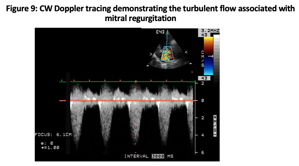
Secondly, if the ultrasound beam hits scatterers of differing velocities, a range of frequency shifts,fd, will be present in the returning echos. The fact that multiple scatterer velocities are presentprovides an important diagnostic clue and indicates that “turbulence“1 is present in the flowpattern. A narrow range of frequencies (velocities) at some instant indicates that scatterers aremoving in unison (flow is “laminar”) while a broad range of frequencies indicates “disturbed” flow.In the normal heart and great vessels, flow is normally “laminar” so any deviation from this patternis abnormal. The turbulent pattern is seen whenever flow into a rapidly expanding region occurs;examples include the flow distal to a stenotic valve, on the backflow side of a regurgitant valve, andthe downstream side of a PDA (pulmonary artery) or VSD (RV).
Three main modes of Doppler examination are employed:
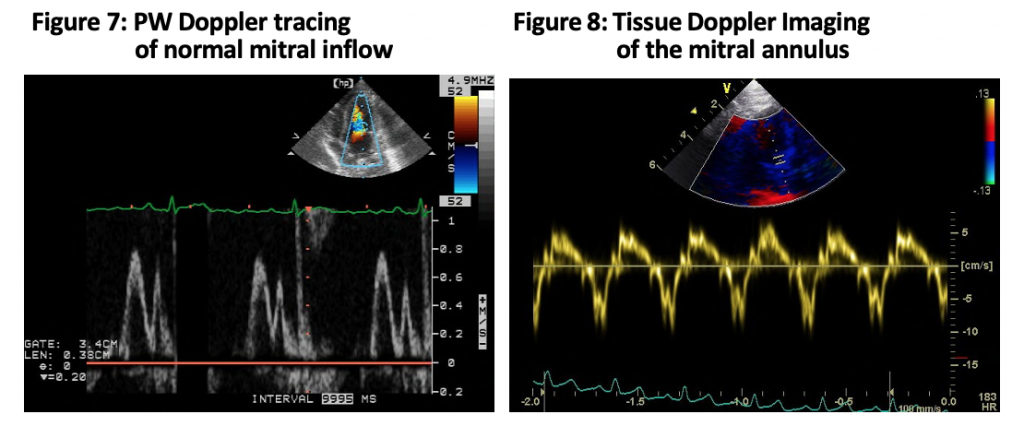
- Pulsed wave Doppler (Figure 7) displays blood velocity from a small region within the heart orblood vessel, called a sample volume, on a strip chart with time as the x-axis. It is used typically in a spectral mode in which a range of velocities can be represented at each time coordinate using the gray scale to indicate the intensity of the signal. Therefore at each instant in time on the x-axis (time), a distribution of velocities within the sample volume can be represented on the y-axis (velocity). Flow velocity signals may showthat sound scattering packets of blood are moving at nearly the same velocity as in laminar flow, as indicated by a narrow spectral distribution a particular moment in time (e.g. Figure 7), or that a wide range of velocities is present as occurs with turbulent flow, indicated by spectral broadening. The significance of this determination is that turbulence is closely associated with flow across abnormal valves or communications (VSD, PDA) and the turbulence occurs immediately downstream of the abnormality. Therefore pulsed-wave spectral Doppler allows determination of the location and timing of turbulence which is a diagnostic aid.
- Tissue Doppler Imaging (TDI) (Figure 8) is a variation of pulsed wave Doppler in which the velocity of myocardial motion, rather than blood flow velocity, is measured. This modality is increasing in prevalence and may provide useful information on diastolicand systolic myocardial function, as well as cardiac filling pressures.
- Continuous wave Doppler(CW) (Figure 9) The primary difference between PW and CW Doppler is that PW emits ultrasound in short bursts, while receiving return echos only during a short interval at a precisely determined time after each burst. For this reason, PW allows measurement of blood velocity from a specific depth, corresponding to the round trip time of the ultrasound. This technique, however, limits the maximal velocity which can beunambiguously measured by PW due to a phenomenon known as aliasing. Thus, PW Doppleris best for determining the exact location of abnormal turbulent flows and for displaying normal low velocity flow signals. Continuous-wave Doppler circumvents the aliasing problem and allows high blood flow velocities to be measured. Therefore, it is used in quantifying maximal blood flow velocity which is very helpful in grading the severity of stenotic lesions where peak velocity tends to increase as valve area decreases. It is not possible to locate the depth at which abnormal signals arise with CW, however, so that use of CW and PW are complementary.
One of the primary uses for CWD is for quantification of peak ejection velocity through orificesand valves. From this information an estimate of the pressure drop across a valve can be made,as would be determined from cardiac catheterization, using a simplified expression of fluidenergy conservation (Bernoulli equation). A fluid particle approaching a stenotic orifice mustaccelerate since the average velocity of flow is simply the flow rate (cm3/sec) divided by thecross-sectional area of the valve (cm2). In gaining this kinetic energy, the particle must lose”pressure energy” for energy to be conserved (not created). Thus, according to Bernoulli, the pressure drops as the square of the velocity increase. In clinicalDoppler, Bernoulli’s equation is typically simplified to: P = 4V^2
where P is the pressure drop across the valve in mmHg, and V is the peak velocity measured inmeters/sec by CWD at the valve (you should be familiar with this equation and be comfortableapplying it!). This approach has yielded reasonable correlation with cardiac cath derivedpressure gradients, but with significant uncertainty for individual cases. It has, nonetheless,been useful as a clinical index of stenosis severity and can be used to estimate systemic orpulmonary arterial blood pressures when mitral or tricuspid regurgitation is present, respectively. - Color flow mapping allows for a real-time two-dimensional tomographic image of the movingheart with color overlaid to represent the velocity of blood flow within the heart and great vessels. Laminar flow velocity is usually indicated as red when flow is towards the transducer, and blue when it is away from the transducer (i.e. BART – [Blue Away, Red Towards]). Like PW Doppler, CF locates the position at which velocities occur but displays them in ananatomically meaningful format. Likewise, accurate measurement of high flow velocity is limited by aliasing. With CF Doppler, a color variance map can be used to indicate a range of velocities within a region so that flow disturbances due to turbulence can be easily appreciated. Color-flow Doppler is best for rapid identification of abnormal flow patterns, such as intracardiac shunts and valvular stenosis or regurgitation, and for qualitatively grading the severity of such lesions from the spatial extent of abnormal flows.
References:
- Tilley LP, Smith FWK, Oyama M, et al. Echocardiography and Doppler Ultrasound, In: Manual of Canine and Feline Cardiology, 4th ed. Saunders, 2007.
- Boon JA. Veterinary Echocardiography, 2nd ed. Wiley-Blackwell, 2011.
- Fox PR, Sisson DD, Moise NS. Textbook of Canine and Feline Cardiology: Principles and Clinical Practice. Saunders, 1999.
