February 12, 2023
For this CAD assignment, we were asked to model/ design something in 3D and post a few renderings on our homepage.
I have a decent amount of experience with CAD in Solidworks; I took Engineering Design I (ME40), a mechanical engineering class, in which we had simple weekly assignments in Solidworks and had a final project where we needed to model an appliance we were assigned. Attached below are the renderings of the homework I had to do.
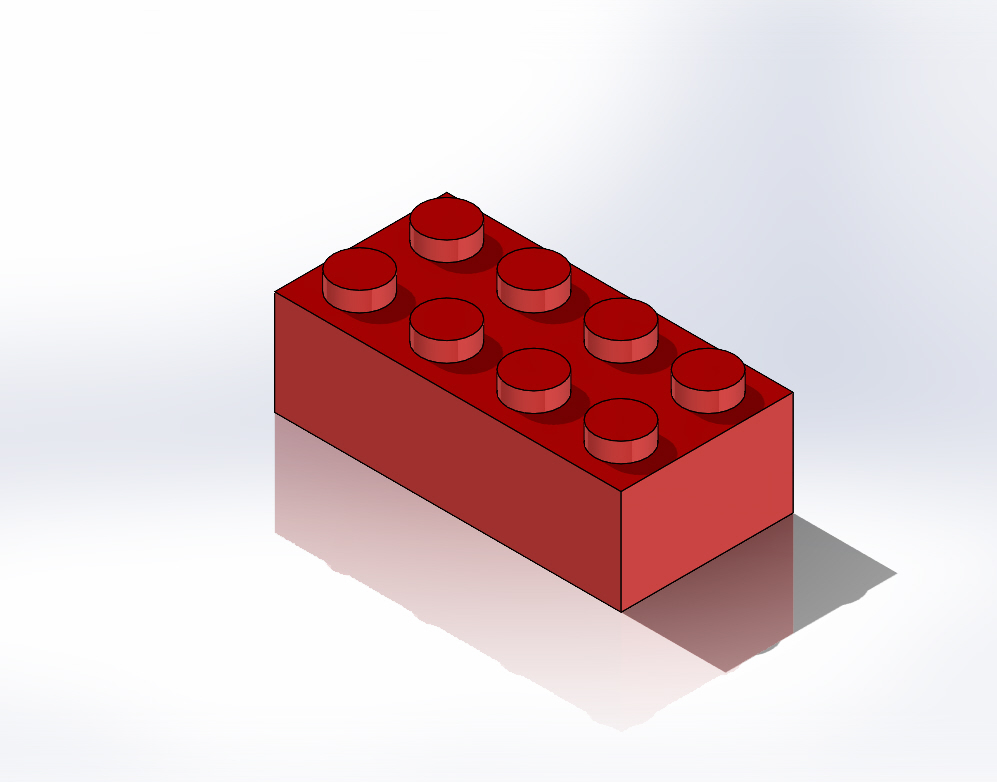
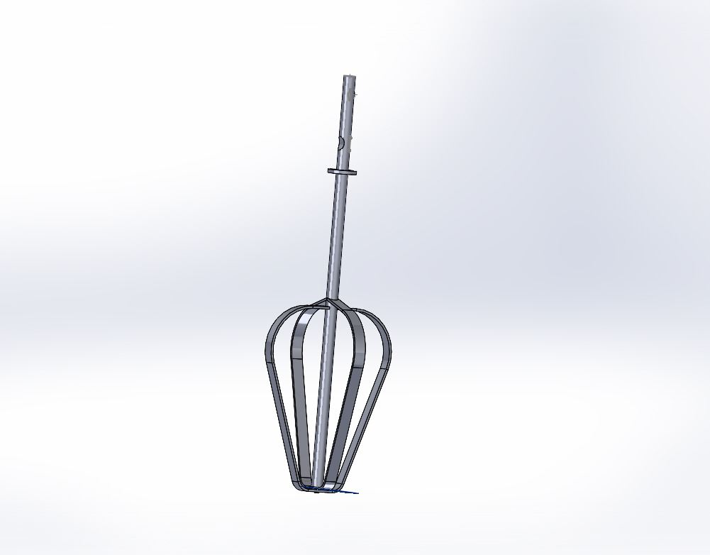
For this homework, I wanted to challenge myself with complex shapes and using extrusion/ cut in simple ways. I had used some complex shapes in other homeworks, seen above, but I have not used Solidworks in a while. I also unfortunately suffered from some sickness for the last week, that rendered my time in Solidworks to be limited. I had not used loft extrusion in a while and had never use a spline before for designing my shapes. I decided to choose a pretty complex shape: a canoe. I worked as a waterfront specialist and as a TWO (Tufts Wilderness Orientation) leader, so I am very familiar with the shape and look of a canoe. I decided to render one of the canoes from my past TWO expedition of summer 2022.


I used Solidworks exclusively for this design. I did all measurements in mm and used a reference picture as a designed to get correct proportions and measurements.
I started by making an ellipse on the top plane.
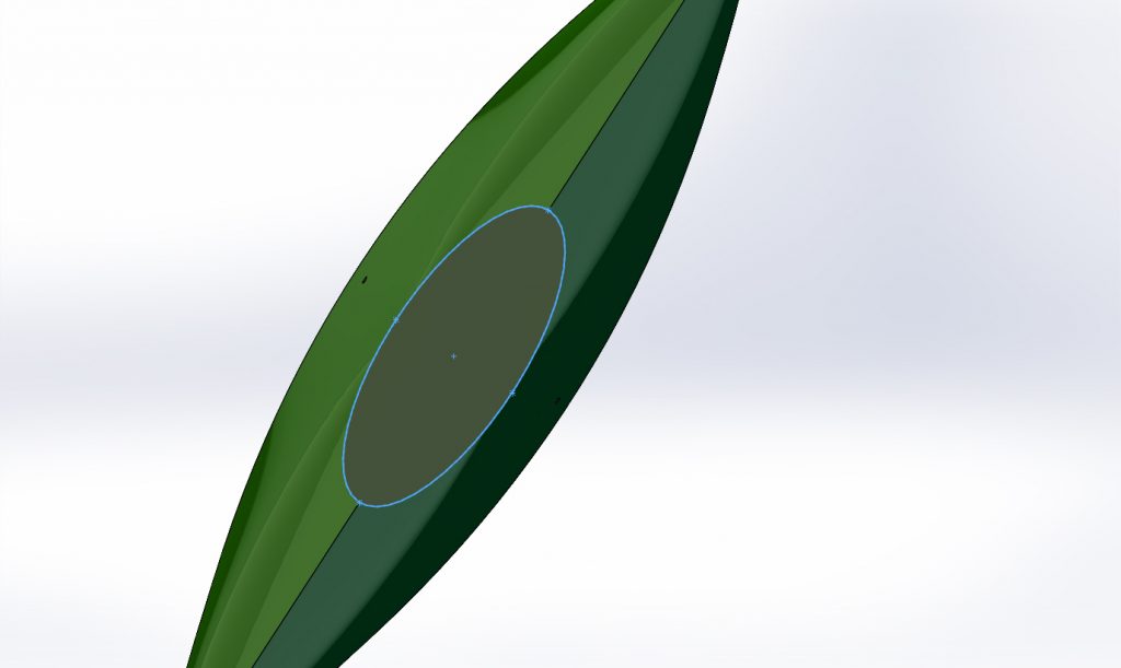
I then made a plan 30 mm above the top plane and made the ellipse with the pointed tip shape using the spline tool.
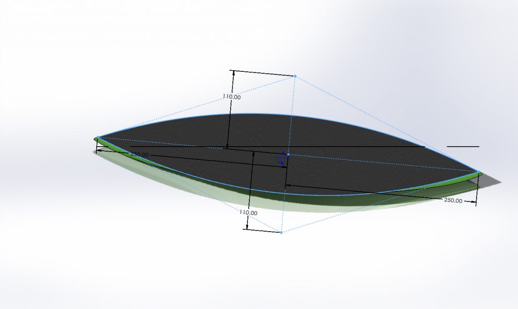
I then made a plan perpendicular to these two plane so that I could make the sides using the spline tool.
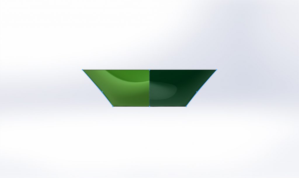
I then made a plane perpendicular to that plane to make the sides of the length of the canoe using the spline tool.
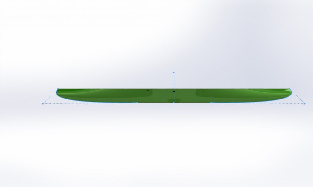
After, I use the loft extrusion tool to extrude from the small ellipse to the larger ellipse with the pointed ends, and used the splined lines made for the sides of length and width as the guide lines.
Then, I used the offset entities tool to offset the ellipse with the pointed ends shape to be inwardly offset so that I could extrude cut into the base.

Then, I created two rectangles on opposite ends parallel to the length of the canoe and extruded them both ways up to the surface of the base to make the seats.

Then I made a circle in that same plane and extruded it the same as the seats to make the thwarts of the canoe.
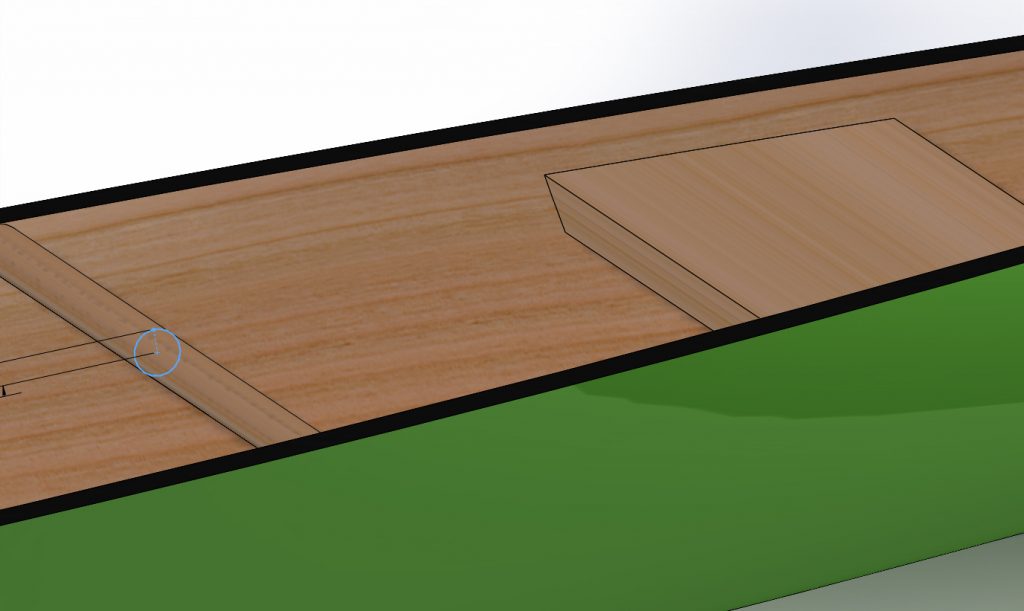
Then I used the linear pattern tool to make the second thwart.

I made a triangle shape on both sides of the canoe and extruded 1 mm downwards so that the decks were made.
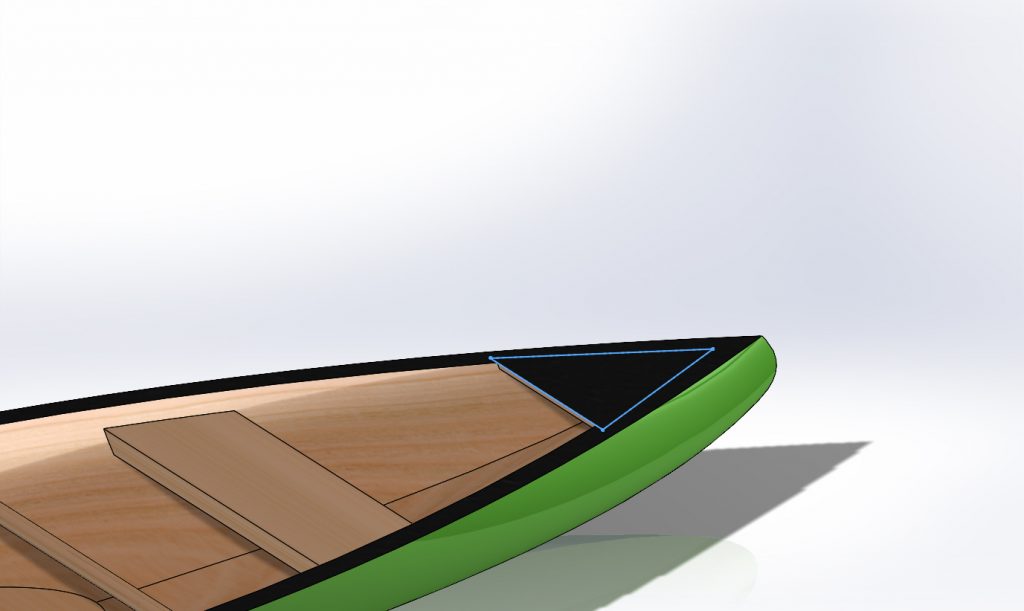
Then, I made another circular shape, but larger, on the same plane as the seats and the thwarts were made, and then extruded both directions for the yoke.
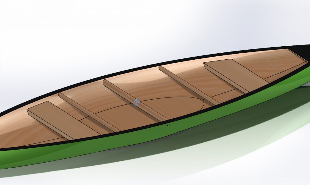
I went back to the deck shapes and made a trapezoid shape and extrude cut blindly 1 mm through the decks to make the handles.

Finally, I made trapezoid shapes on the sides of the seats to better portray the shape of the seats of the canoe. This was challenging because the side of the seats is not a straight line- I had to use an arc to make the correct shape so that the whole seat was extruded through and would not leave a weird sliver of seat left.

After about 3 hours of Solidworks, I was able to finish with an end product I am very proud of! I incorporated a lot of colors, which was also a goal I wanted. I haven’t used color and texture a lot in Solidworks before but I believe that that adds a finishing aspect to the piece.
Finally, I changed the color to be a darker green and my canoe was complete!

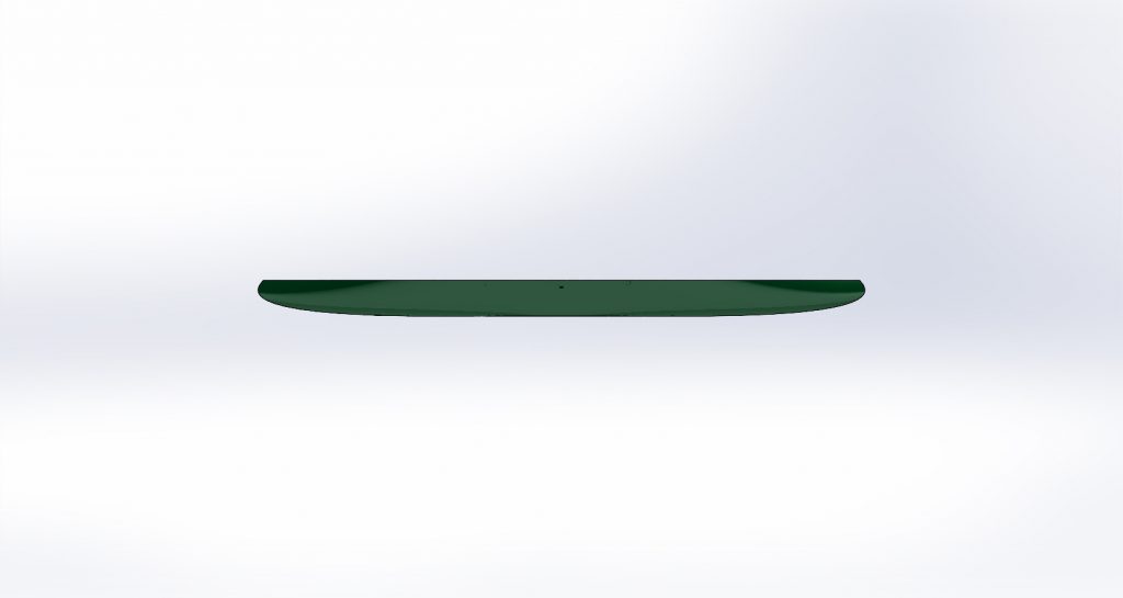
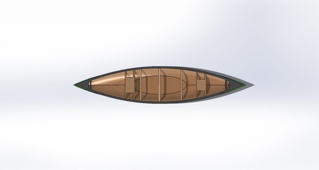

The canoe shape is interesting and a challenge: it is not necessarily a rectangle or a curve prism, but has an upward slope from an ellipse base to end in a pointed ellipse. Designing the shape of the canoe was difficult because I was at first unsure how to create the desired shape. I used a spline took to make the rounded edges of the canoe, as well as the pointed ellipse shape for the top shape. Using the spline tool was a little difficult to at first control, but after I understood exactly how to use it, it was extremely useful.
One of the biggest challenges I encountered was extrude cutting. It was difficult to extrude cut through the seats and the decks to create handles and not extrude into the base of the canoe (pictured below). I resolved this issue by instead of choosing “blind” under extrude cut, I chose “Up to Surface” and then chose the surface of the base of the canoe. This solved most of my extrusion problems.

In the future, I want to better set my planes so that they all build off each other/ set my center lines in a certain way where I would be able to change one feature of the design without having to change every single feature manually. For example, I thought the canoe seemed a little shallow so I wanted to increase it’s height. When I changed the plane offset from the base place to be 20 more mm, it appeared the other features I had made were not connected to that plane that was changed, so although the canoe increased in height, the other features such as the seats, thwart, and yoke did not increase in height and were in the wrong place. This means that those features were defined not by the plane, but by some line with a set value. So, when the plane was changed, that did not change the height of the set line or the features. In the future, I want to learn how to define my features based on the planes that are defined on top of each other so that if one feature is changed in the design, all other features will adjust and I will not have to do that manually.
In the future, I would also like to be able to add some more features like a criss-cross mat on the seat or more extruding/ shape features on the yoke. Overall, I am very proud of my final product, almost as proud as I am of my 10 first years for finishing our 5 day canoe trip (pictured below)!

