
February 28, 2023
Hello and welcome back to my BME 66 page! In this week’s update, I completed the Laser Cutting Homework. The homework was to design, make, and document a 3-D object using the laser cutter.
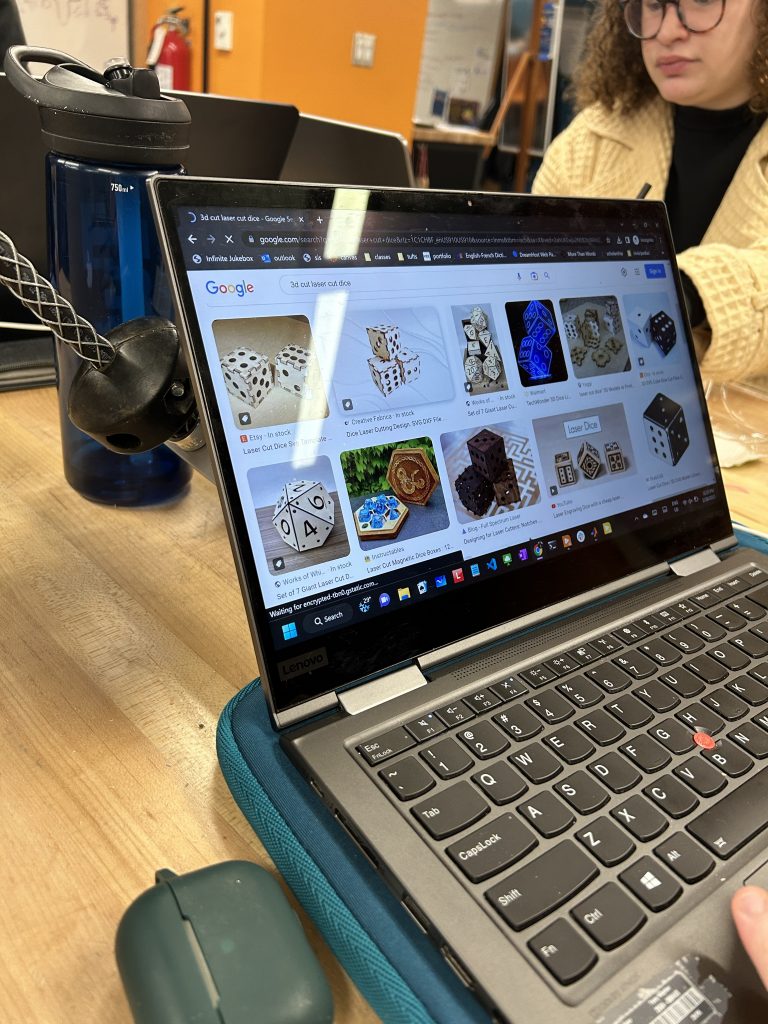
To start my adventure of laser cutting off, I trekked over to Nolop in the SEC. I was not going to let the overwhelming amount of Mechanical Engineers get in my way of laser cutting! (And thankfully my friend Rachel was there to help). Upon arriving to Nolop, I had little to no idea of what I wanted to fabricate. Rachel suggested that I make a simple box, and to that I said “mmmmm maybe not.” Then I realized, “wait, am I going to have to make the notches for my design?” Rachel showed me this program called MakerCase, which designs you simple notches boxes and other shapes for laser cutting. As Rachel was going through images online of what MakerCase can create, an image caught my interest: a pair of dice.
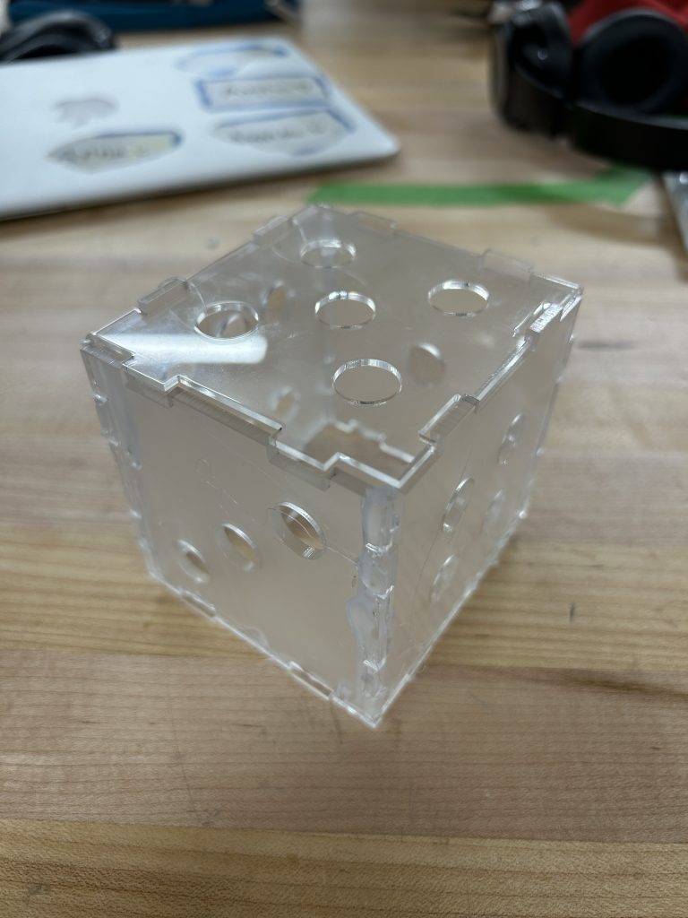
You may be thinking, “Anna, isn’t a dice just a box with more holes cut into it?” And yes, yes it is, but it is a much more interesting box. I could not find a MakerCase dxf file for a die, so I decided to make my own (and because that was a part of the assignment)
I opened up SolidWorks and began to work away. I made a square 3 in x 3 in. Then, I made one small rectangle (as the notch) at the top the square 0.5 in from the edge, 0.15 in in width and 0.5 in in length. I reflected this rectangle over a vertical centerline to create a rectangle on the other side of the top of the square. Then I reflected both rectangles over a horizontal centerline to create a pair of rectangles on the bottom of the square. I repeated that process to create rectangles on the other sides of the square. Finally, I was finished with one side of my die.
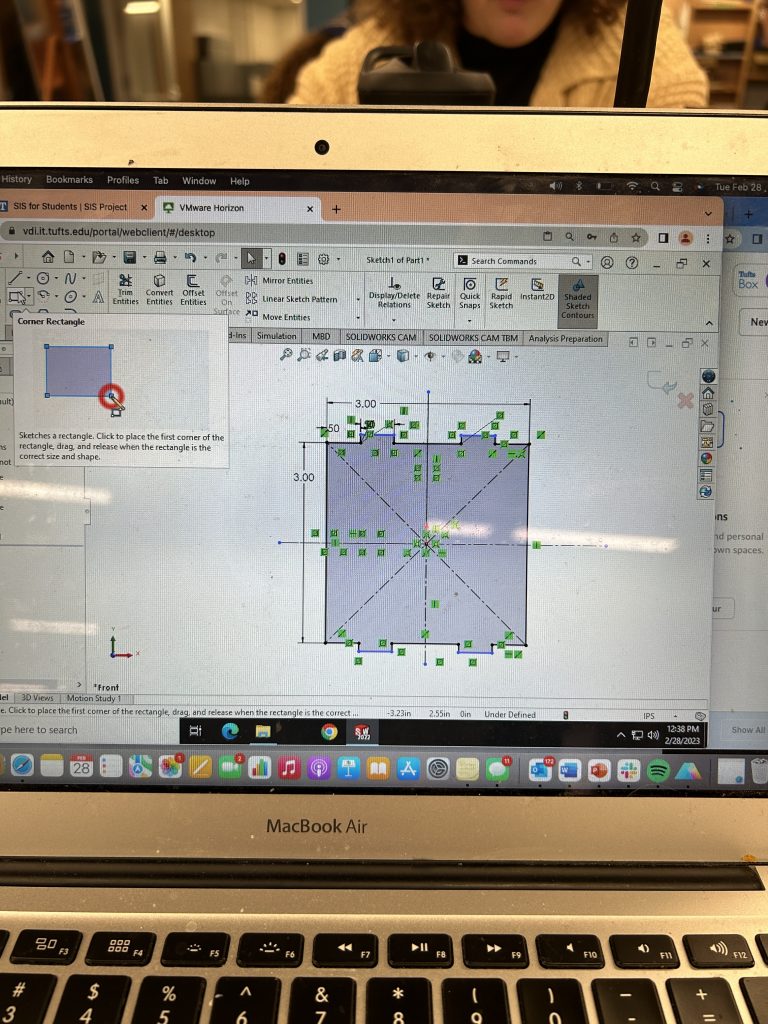
I then started with adding two circles, 0.5 in in diameter and 0.5 in from the center, to represent the number of dots on that side. This would mean that my first side made was the 2 side.
After I made these notches, I realized, wait.. I need inverted notch holes for the pieces to fit together. So, I reflected the whole side of the die over a line to create another side. I erased the rectangle notches and instead with the line tool drew in notch holes that were 0.15 in width, 0.5 in in length, and 0.5 in from the edge to match up with the notches I already made. I added a circle in the middle, 0.5 in in diameter, so that that side was the 1 side.
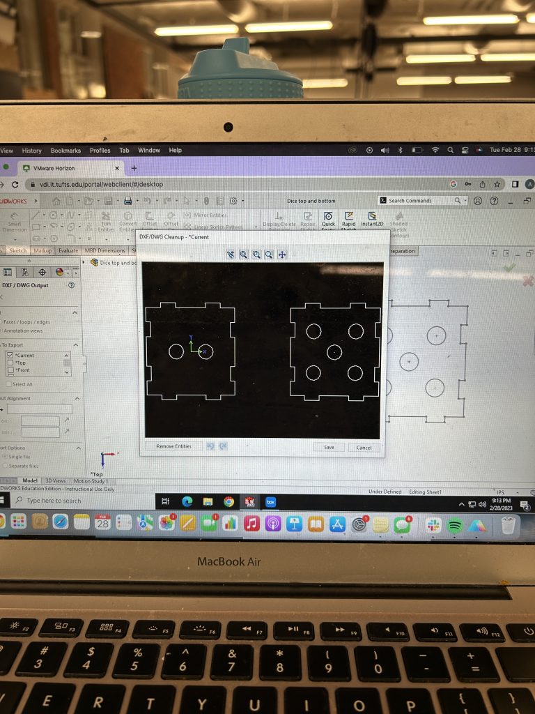
I found a maker case file for a cube and I compared my design to the cube to make sure I was on the right track. In my not so careful scan, I thought that I was. It seemed like there were 2 different shapes for the cube: 4 sides with all notches and 2 sides with all notch holes. That should have raised some flags for me but I was operating off of a few hours of sleep and the great discussion Rachel and I had was distracting me. So, with this assumption in mind, I mirrored the notched side 3 times to create 4 notched sides and I mirrored the notch hole side once to create 2 notch hole sides. Then, I added the different number of circles to each side of the cube. All circles were 0.5 in in diameter and were placed using the vertical, horizontal, and diagonal centerlines.

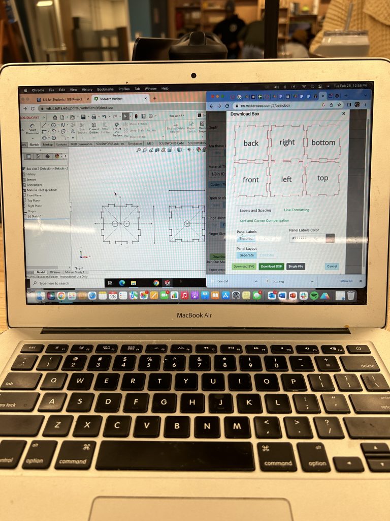
Finally, my design was almost ready. I erased all of the centerlines on all sides (which took a considerable amount of time) and then exported my file as a dxf so that it was a vector drawing and could be opened in Adobe Illustrator on the Laser Cutter in Nolop.

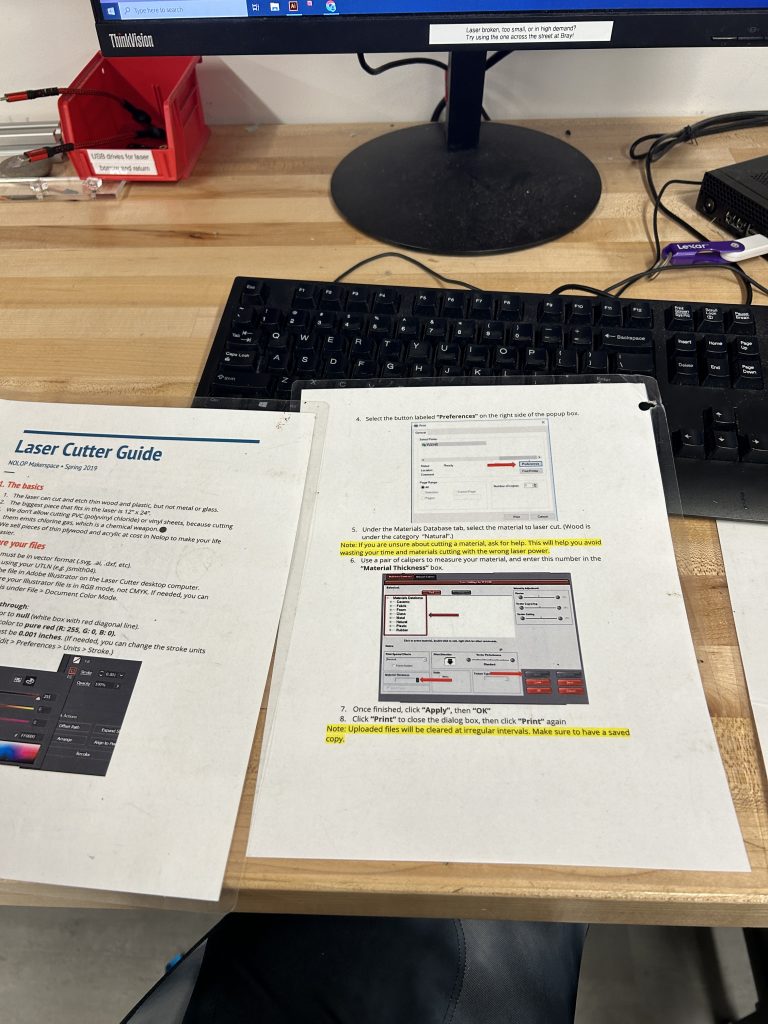
I uploaded my design to my box, logged into my box on the computer set up to the laser printer, and pulled up my design on Adobe Illustrator. I chose my material to be acyrlic solely because Rachel’s friend Alex just used a piece of acrylic and put it into the scrap pile and Rachel said acrylic would be cool. I followed the guideline instructions of the Nolop laster cutter carefully: I made sure the stroke size of my vectors was 0.001 in, I changed them all to red so that they would be completely cut through, I measured my material depth and chose Cast Acrylic as my material, and dragged my design close to the edge so that I would save material. I placed my acrylic into the laser cutter, sent the design to print, opened up the new tab with the laser cutter software, tested the edge cases of my design by moving the laser head to make sure my design would not cut though any existing hole, and pressed the big green button to start.
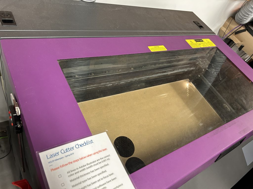
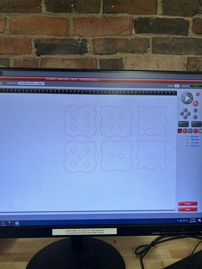
After about 2 minutes, my laser cut was complete! As it was cutting, however, I checked over the sides and their notch configuration again: unfortunately, I realized mid print that I need 3 different shapes: 2 sides with all notches, 2 sides with all notch holes, and 2 sides with notch holes on parallel sides of the square and notches on parallel sides of the squares. So, unfortunately, I predicted that my die cube would not fit together.
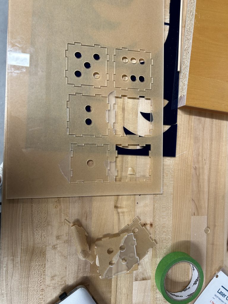
I took my pieces out and unfortunately, side 2 and side 5 did not fit because there were too many notched sides. It was time for my class so I had to leave Nolop but I was motivated to come back later.
I ventured back to Nolop with Rachel (after bribing her with a ride from her house) at around 8:30 pm that same night. I quickly cad’ed up two new sides for the dice with parallel notched sides and parallel notch holes sides on each square. I exported them as a dxf file and uploaded to my box.
I sent those to cutting using the same steps as I had before (it went by a lot quicker now that I had already done it!) and waiting for my sides to be complete.

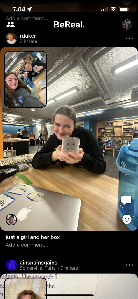
Finally, I peeled away all of the paper off of my acrylic, heated up a hot glue gun, and then glued all my sides together and voila! I now had a fully functional die!
I would like to thank Rachel for going through this journey with me, the lovely Nolop worker who was off duty but was a kind soul and helped me figure out the laser cutter the first time, and the large stock of acrylic that Nolop keeps.
Objects Hard to Fabricate With Traditional Technologies
Laser cutters are high speed, efficient, and precise, which makes this fabrication process a useful tool for creating medical devices. Medical device laser cutting is used extensively in the design and manufacture of medical devices and implants such as stents, heart valves and other medical devices as well as medical tools and components and improves the fit, form and function.
Two traditional ways medical devices are made are CNC milling and injection molding. In CNC( “computerised numerical control”) milling, the machine can process different materials via computer-assisted numerical control. There are drawbacks of CNC milling, such as its high-maintenance. There are follow-up costs for milling as new tools need to be bought regularly. Laser cutting does not create such wear and tear and therefore costs less, even for the smallest shapes and engravings. There are no maintenance costs for laser technology, which guarantees optimal cost control for businesses. By contrast, CNC milling without maintenance is not possible. In injection molding, a mold is made and then a material fills the mold to create the desired shape. 3D printing can be useful in replacement of injection molding because if the desired shape is more flat, a precise drawing can be made for what exact shape the piece needs to be. An example of this would be a functional stability part on a non-custom medical device, such as on a piece of precise surgical equipment or a surgical tool.
There are some downsides of using laser cutting for medical devices. For example, micro-cracks can occur which would result in failure of the device. Material thickness can be a big limiting factor, and most laser cutters can only cut metal between 15 to 20 mm.
Laser cutters seem to be good for square/ flat designs, but do not seem as useful for round designs. For example, the Impella heart pump is a long cylinder shape. It may be difficult to manufacture this shape using a laser cutter because the laser cutter would probably not be able to cut through a brick of metal this large. One solution around this is to do more iterative smaller pieces that fit together, but that may cause more chance of failure.
