3-Point Bend Test Machine Setup
For a 3-Point Bend test, the following fixtures and components are required:
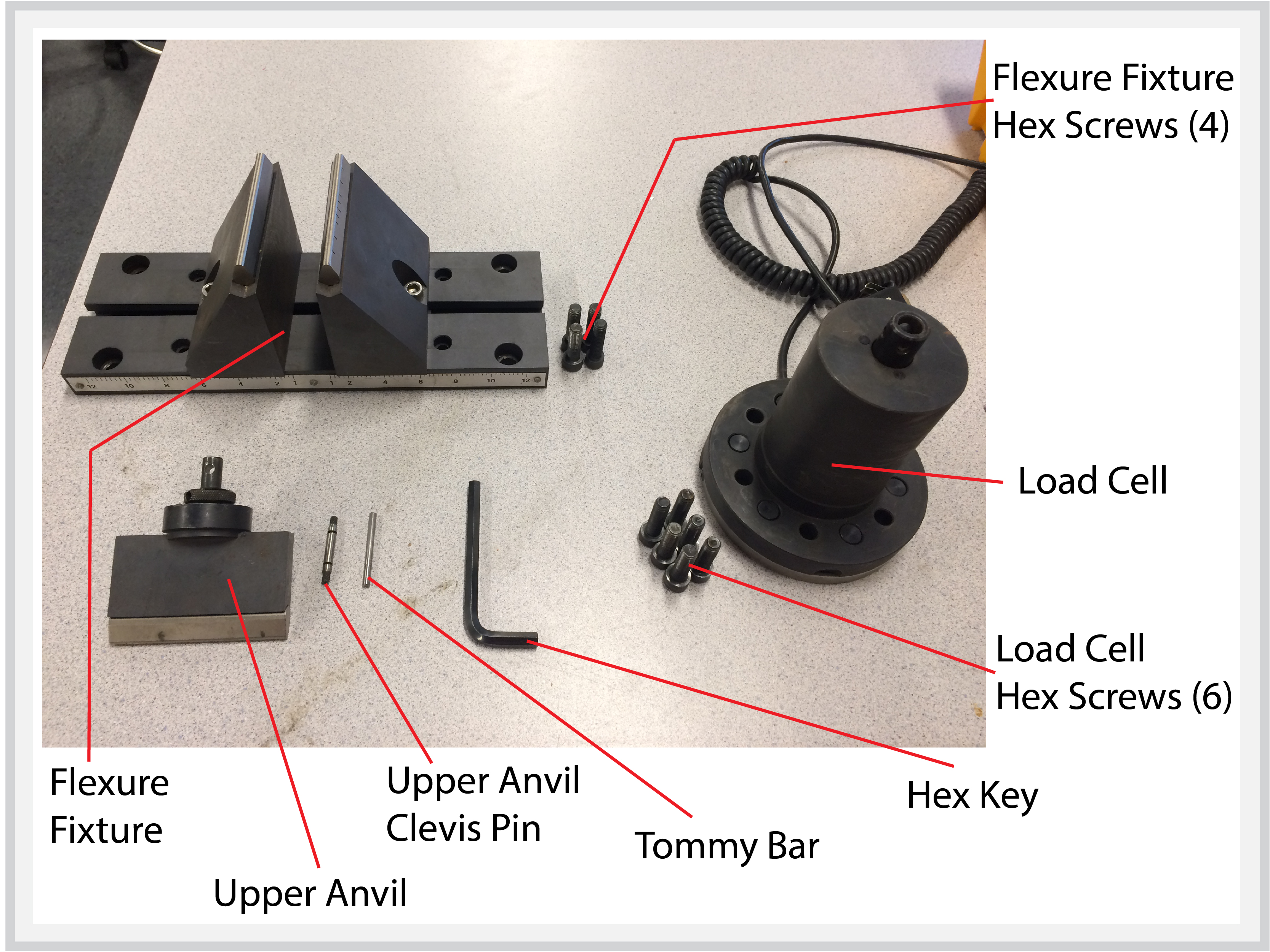
○ Load Cell
○ Load Cell Hex Screws (6)
○ Flexure Fixture
○ Flexure Fixture Hex Screws (4)
○ Upper Anvil
○ Upper Anvil Clevis Pin
○ Tommy Bar
○ Hex Key
1. Install Load Cell
- Make sure there is no Load Cell currently installed in the Load Frame.
- Insert the Load Cell into the top of the Load Frame making sure that it is in the correct orientation (i.e., the wording on the label is facing the operator).
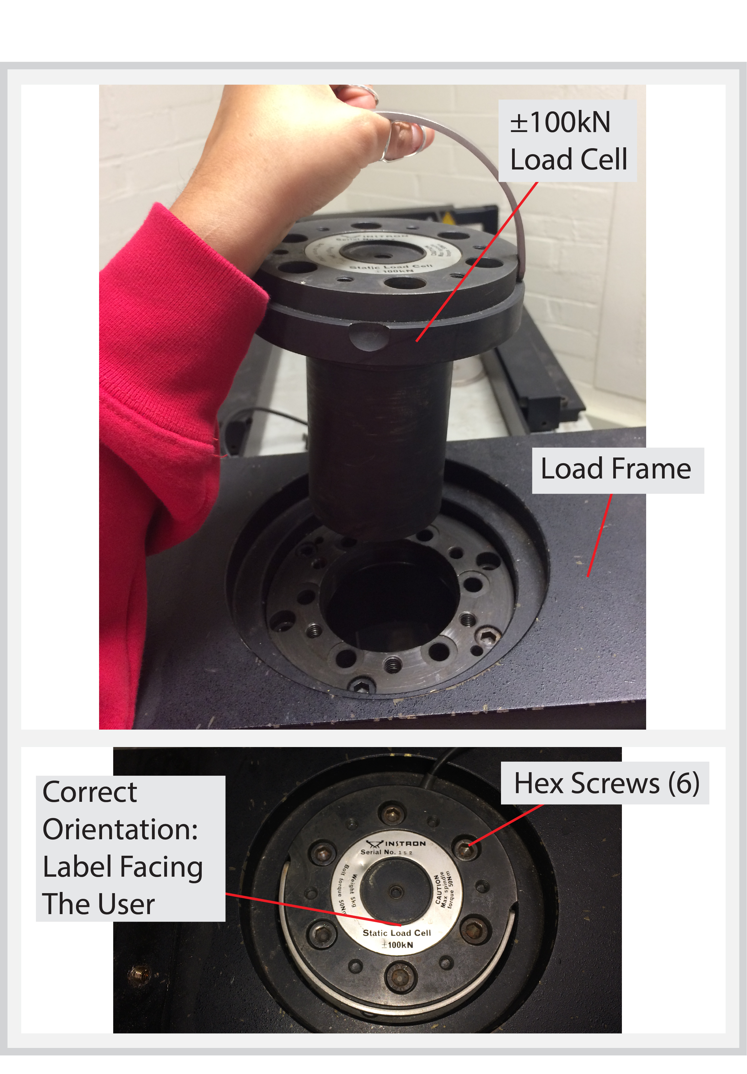
- Attach the Load Cell to the Load Frame using 6 Hex Screws.
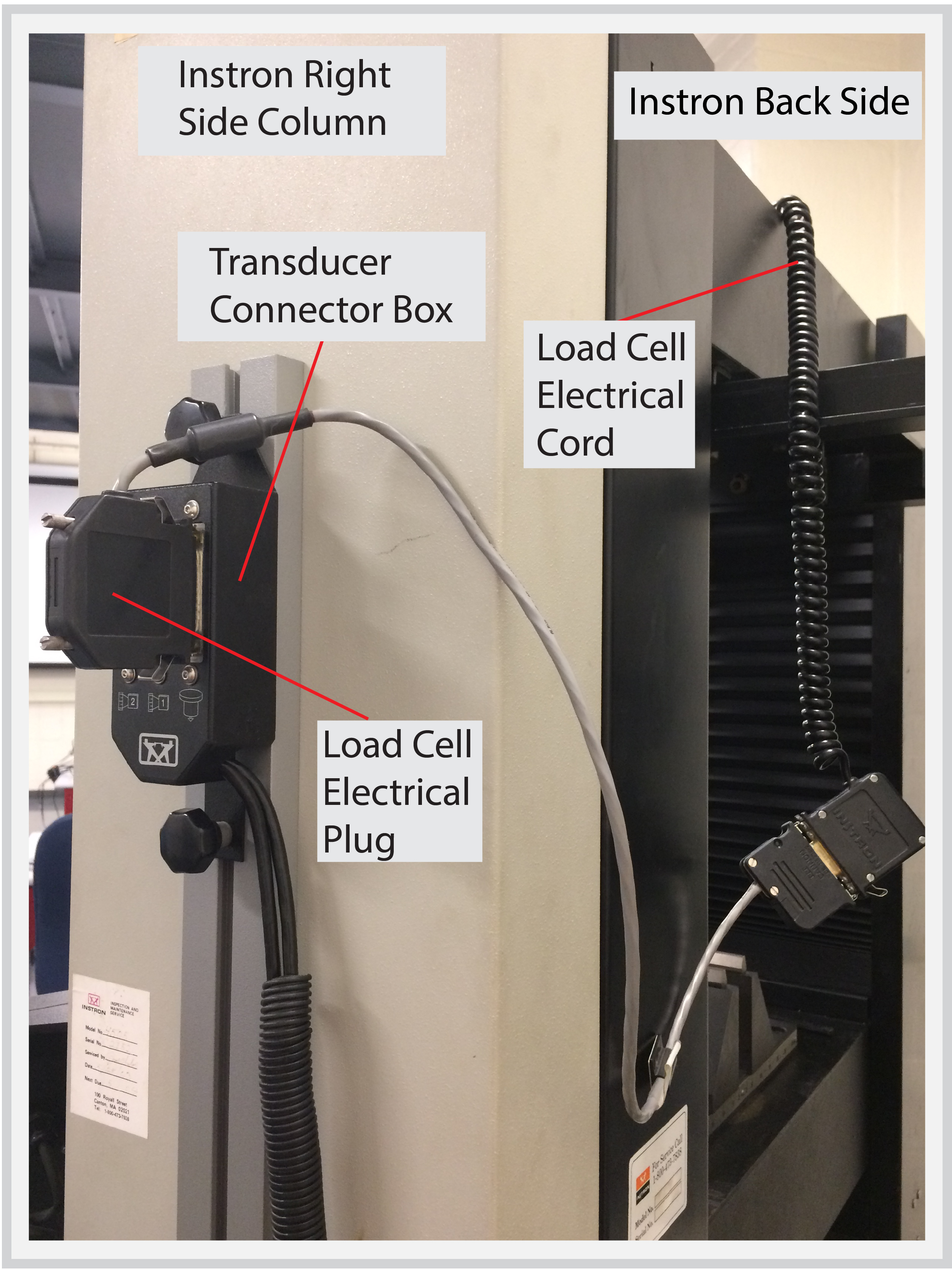
- Plug the Load Cell into the Transducer Connector Box.
- On the Desktop Computer, start up the Bluehill application software. This will enable the jogging operation of the Crosshead.
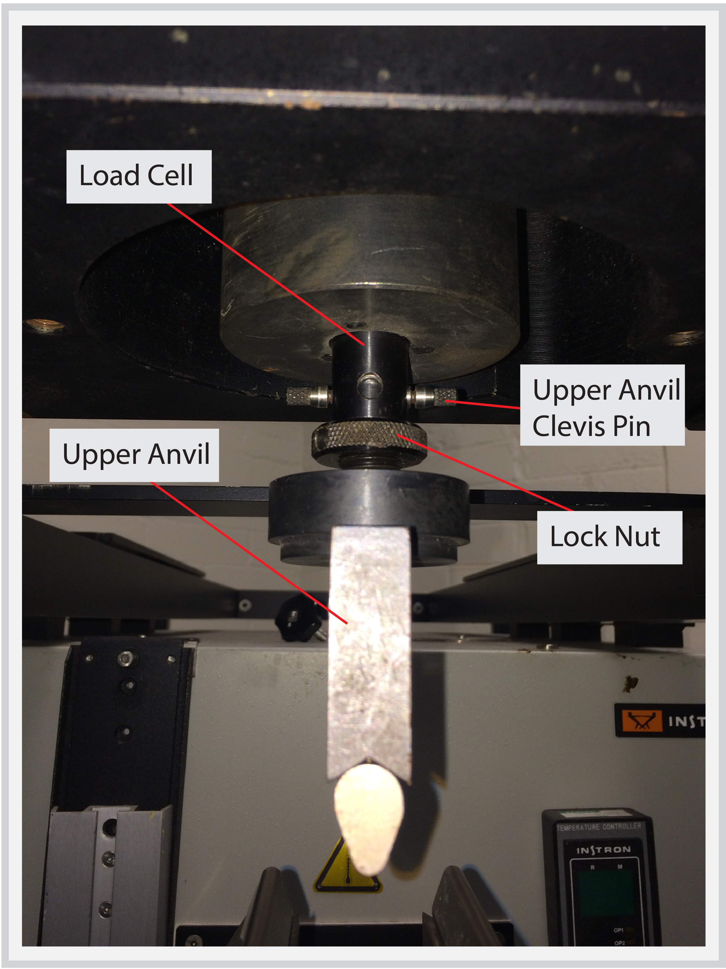
2. Install Upper Anvil
- Insert the Upper Anvil into the Load Cell and secure it with a Clevis Pin.
- Use the Tommy Bar to hand-tighten the Lock Nut against the Load Cell.
3. Install Flexure Fixture
- Make sure all previous fixtures have been removed from the Instron.
- Place the Flexure Fixture onto the Crosshead. The Flexure Fixture should be attached to the Crosshead using 4 Hex Screws.
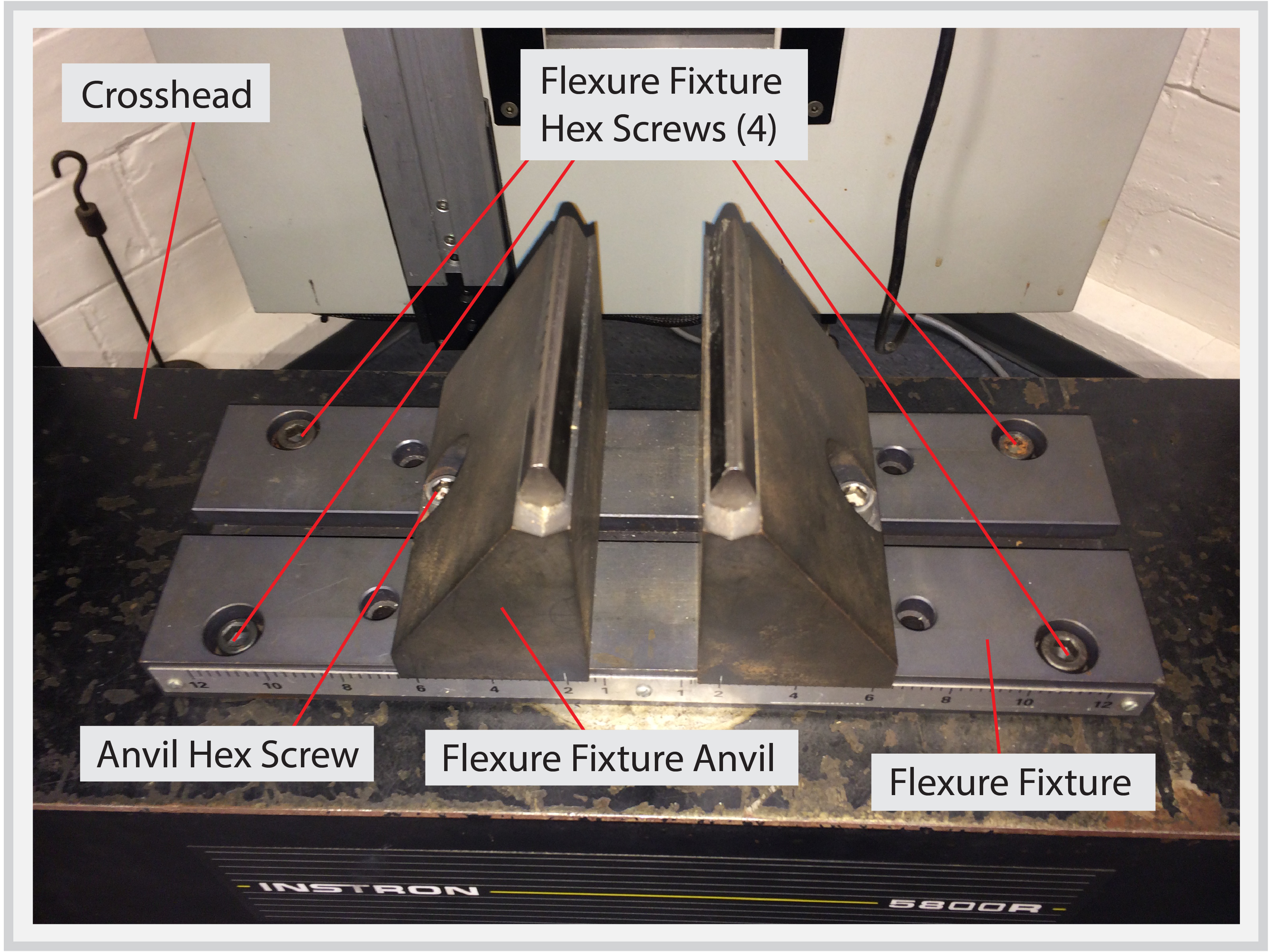
- The span of the Flexure Fixture avils is adjustable by loosening the hex screws located on the anvils. It’s recommended to measure the span between the anvils with calipers to account for any age-related deformation reducing the accuracy of the built-in units of measurement.
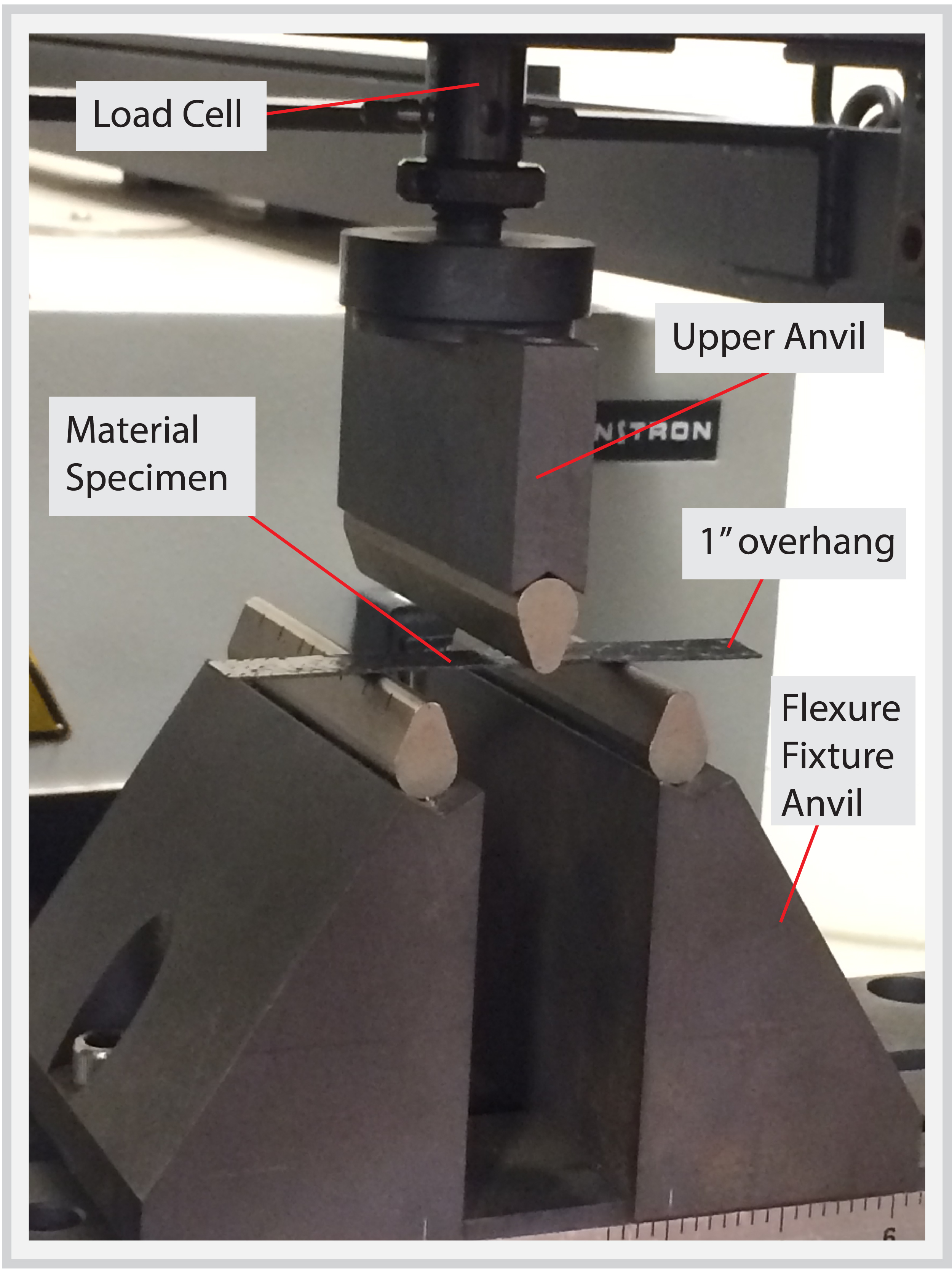
4. Install Material Specimen
- Place the material specimen across the Flexure Fixture anvils. Standard testing protocols usually call for at least a 1″ overhang of material on either side of the Flexure Fixture anvils. However, this may vary based on the material type and geometry of the specimen.
- You are now ready to perform a 3-Point Bend Test. Please refer to the next section on Software Setup for programming and running the test using the Bluehill software.
Next Steps:
- 3-Point Bend Test: Software Setup – page under construction