Category: Summer Internship 2016 (Page 1 of 4)

DI-Wire Computer Stand

A 6’7″ friend of mine came to me asking if I could build a more elegant solution to his makeshift cardboard box computer stand

Photo Aug 12, 2 59 58 PM


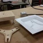
So I decided to make a stand for him using the DI-wire. I started with brainstorming ideas and settled on a final geometric triangular design. The sides would be made using the DI-Wire and the top would be made out of a piece of acrylic

Photo Aug 12, 2 24 36 PM        Photo Aug 12, 2 25 06 PM

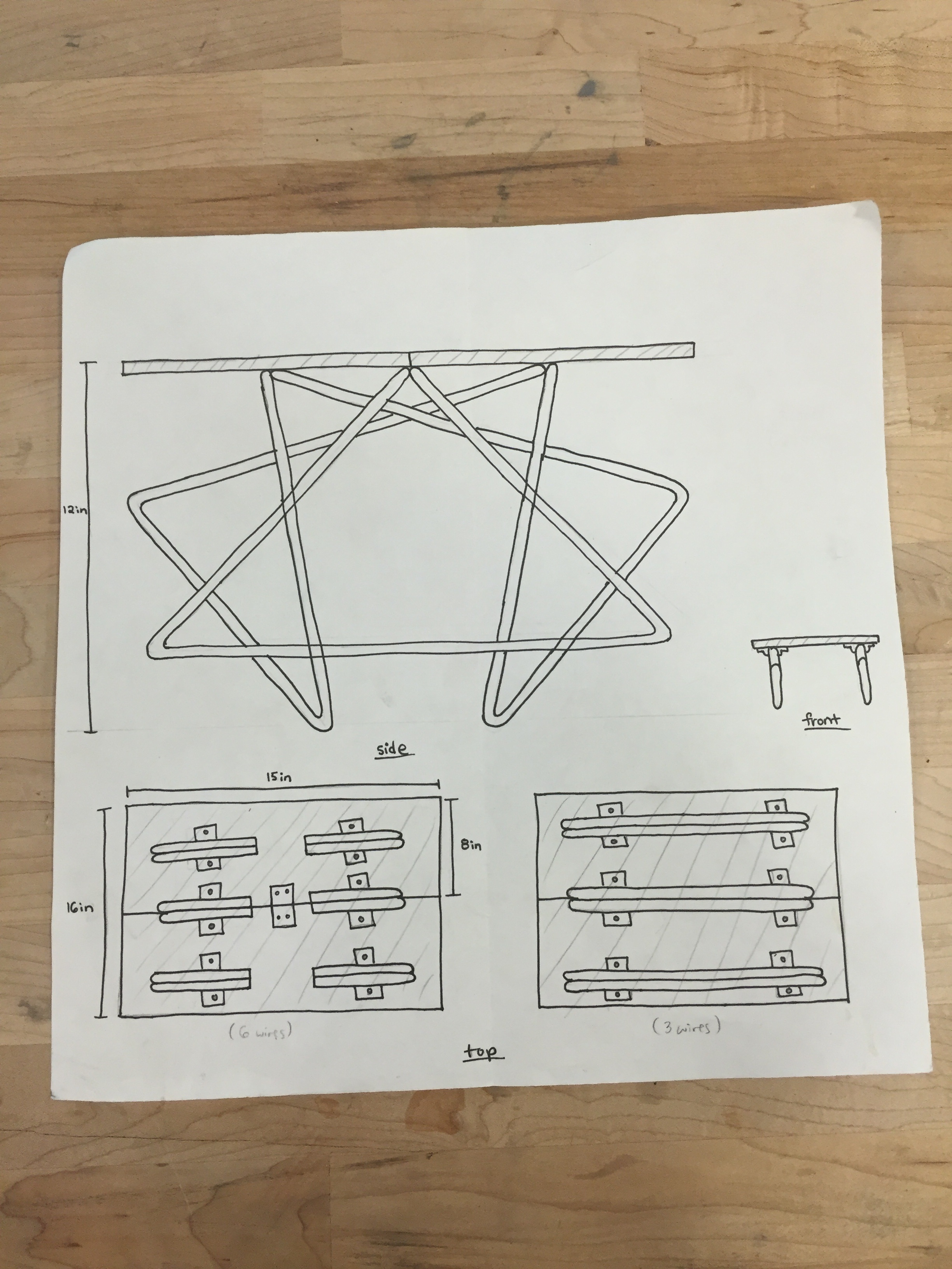
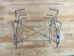
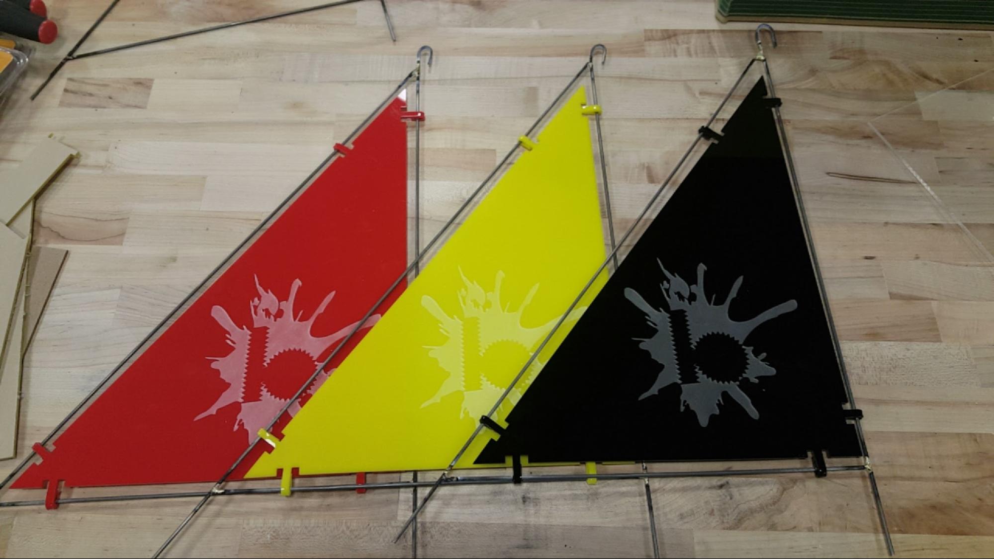
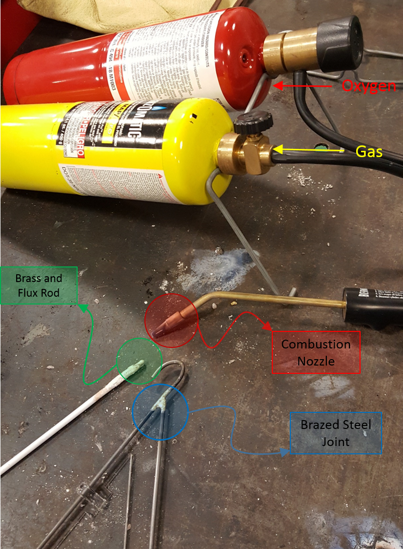
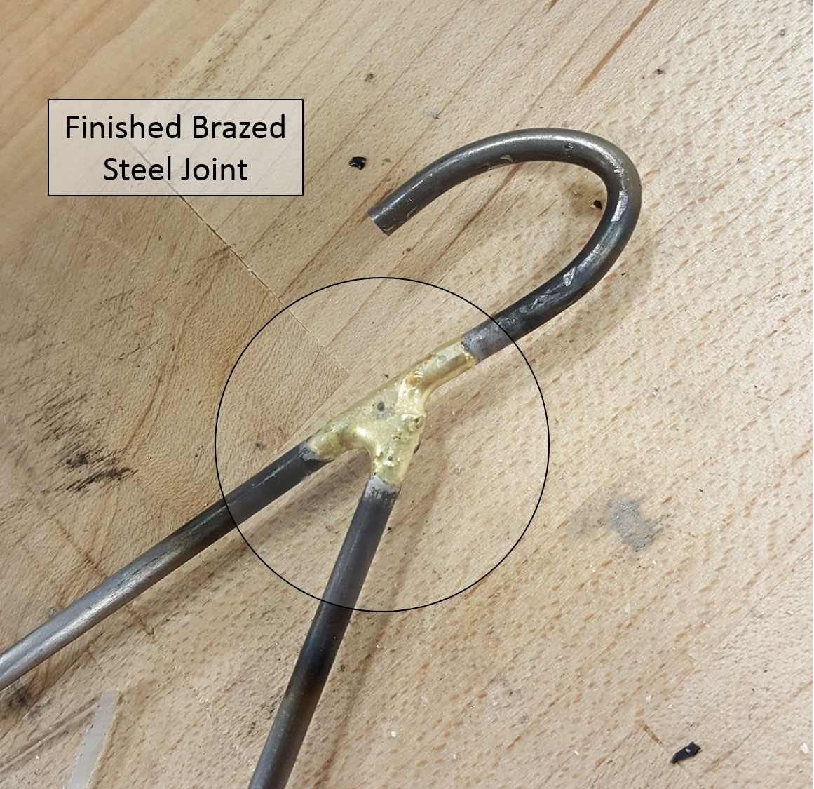
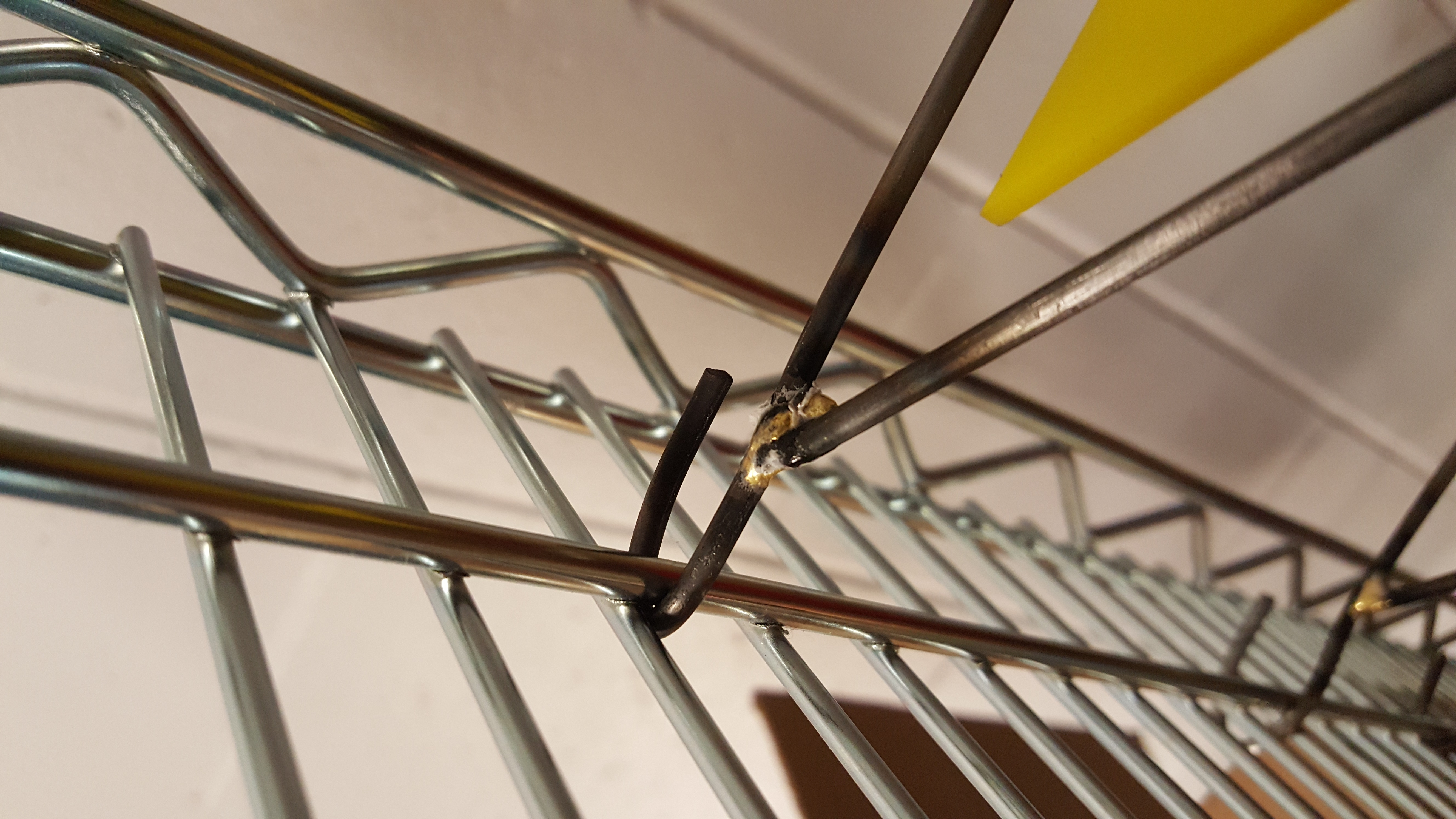
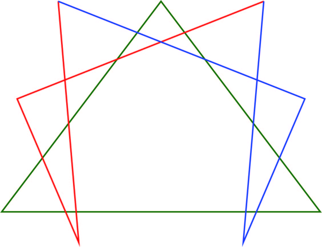
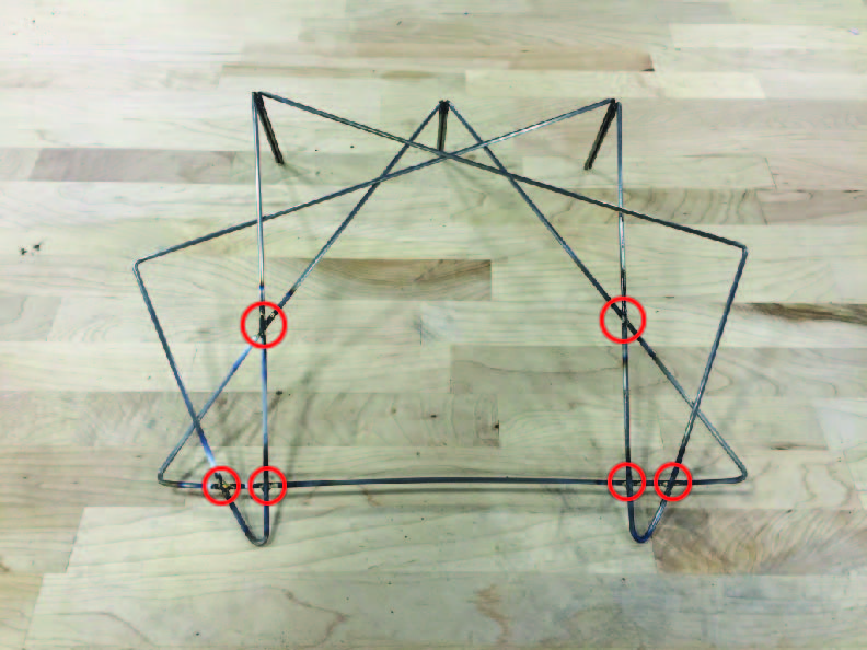
I used the manual function on the DI-Wire to bend three pieces of steel wire into the different triangular shapes (the green, red, and blue shapes) that made up the geometric design. I then used a technique called braising which is like welding but for thinner metals. I braised the top wires together to form the design and then braised six points of the design (the ones circled in red) for structural support.

big stand outline         Photo Jul 15, 1 56 10 PM        Photo Jul 15, 3 18 03 PM                braising

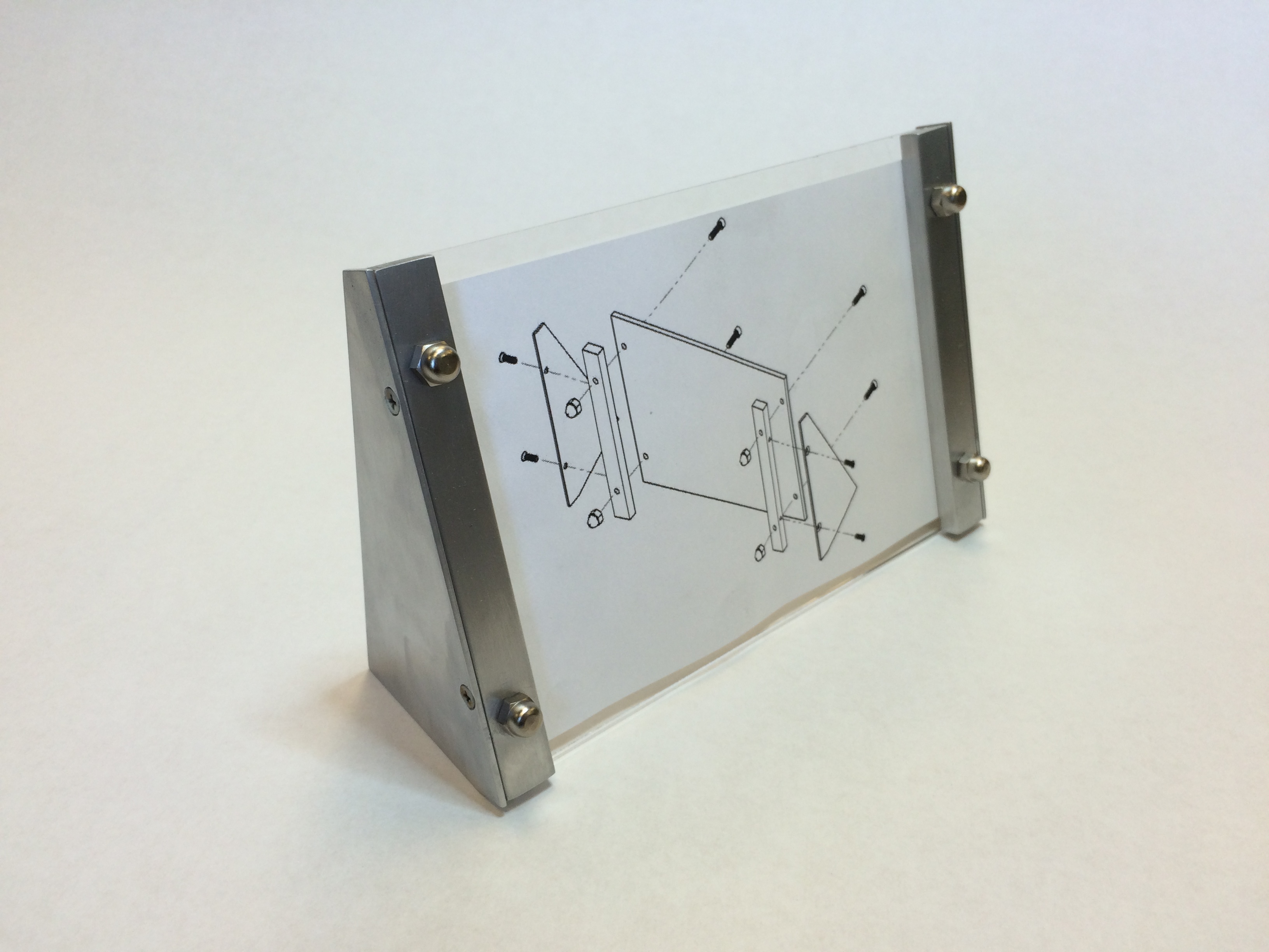
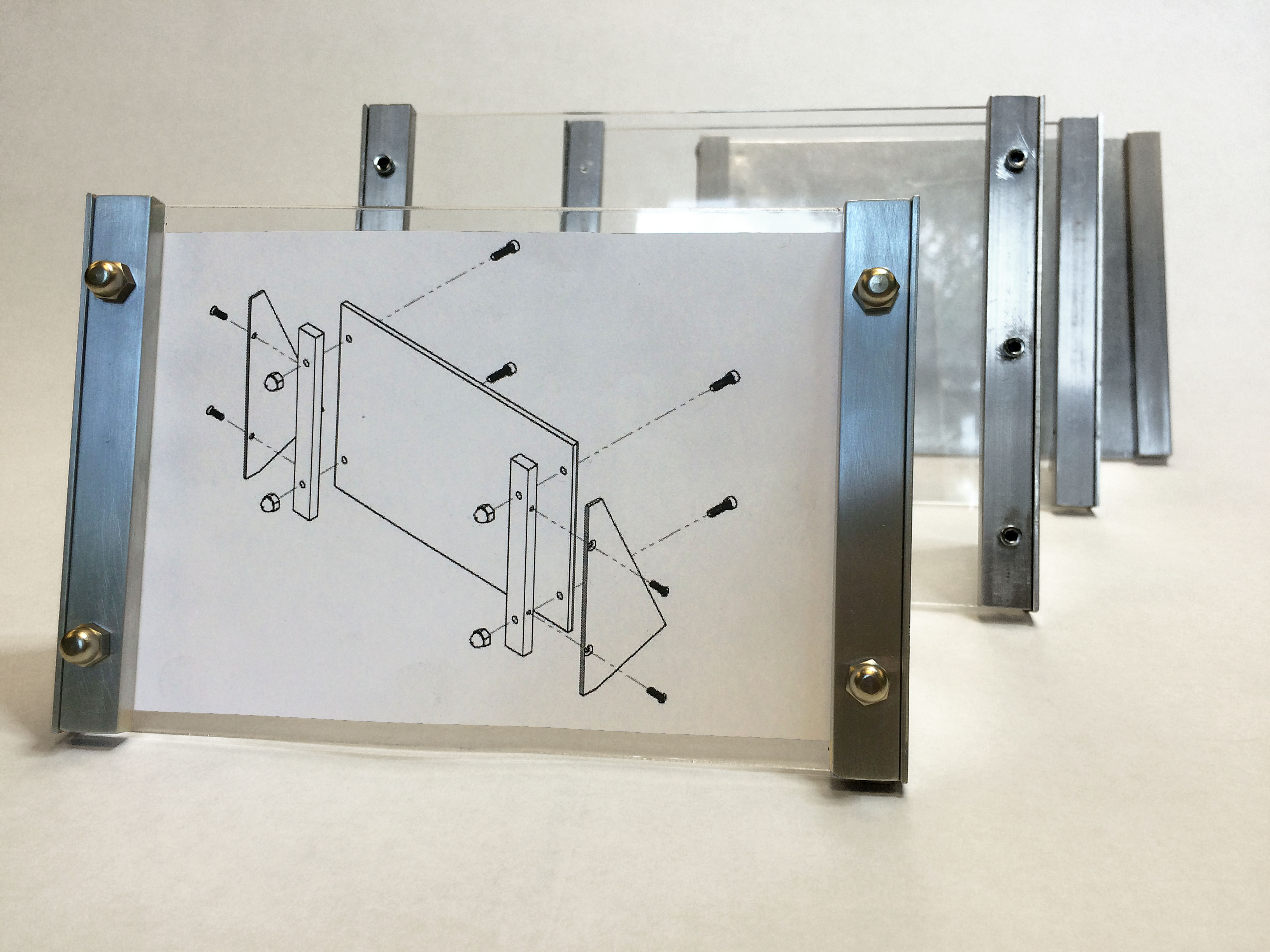
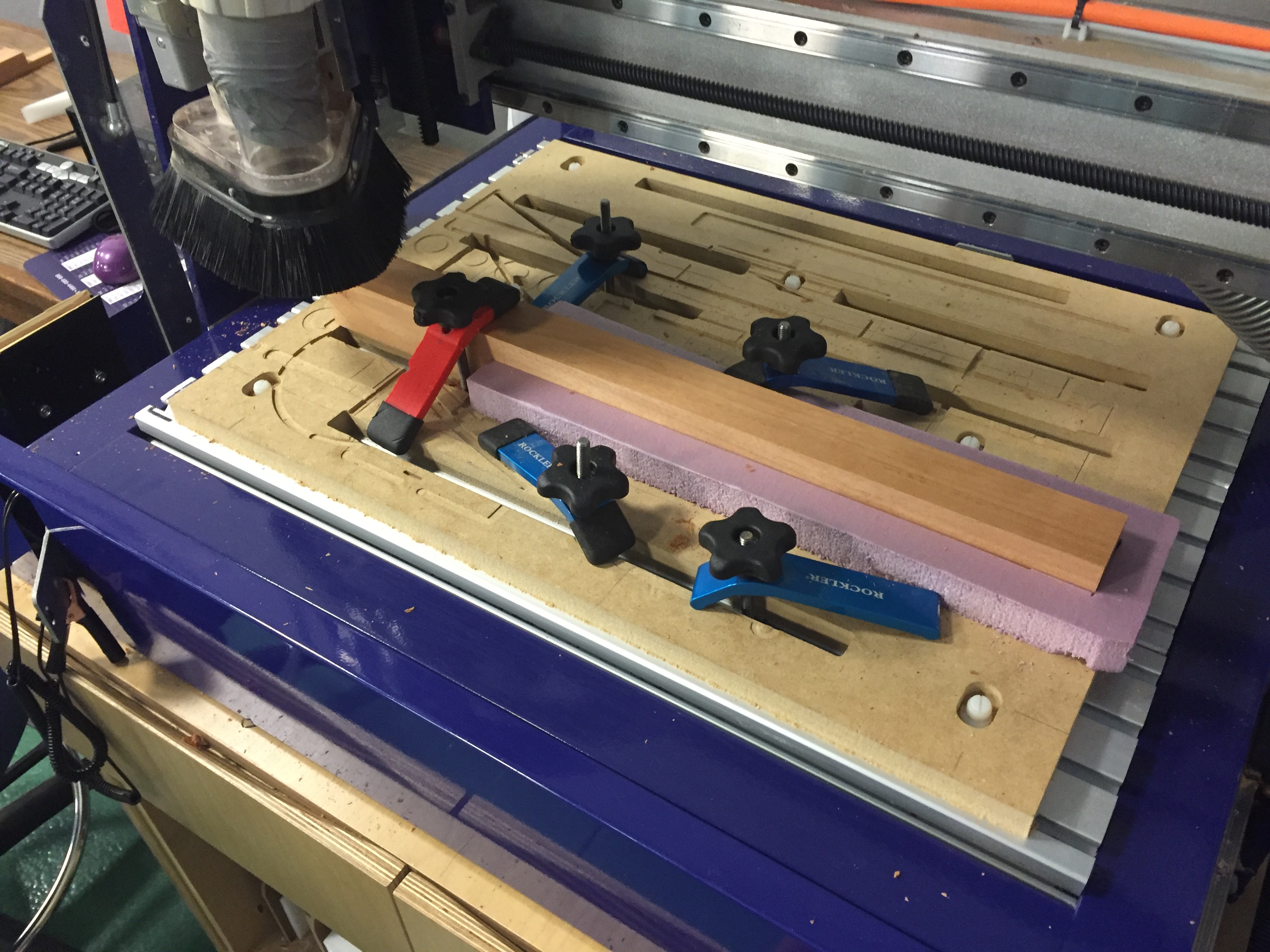
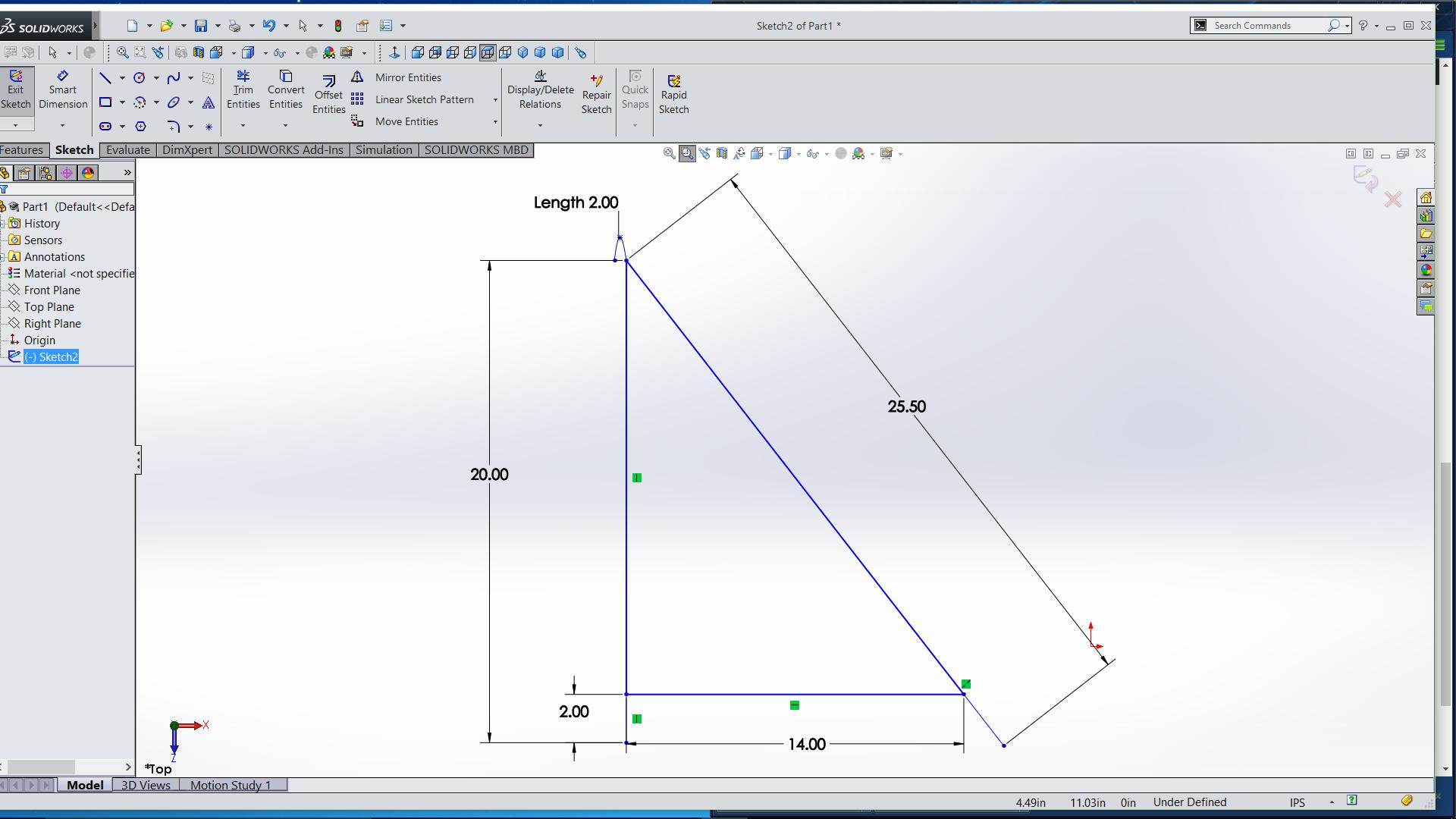
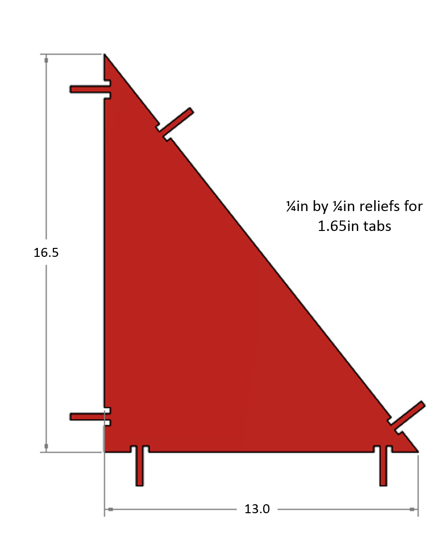
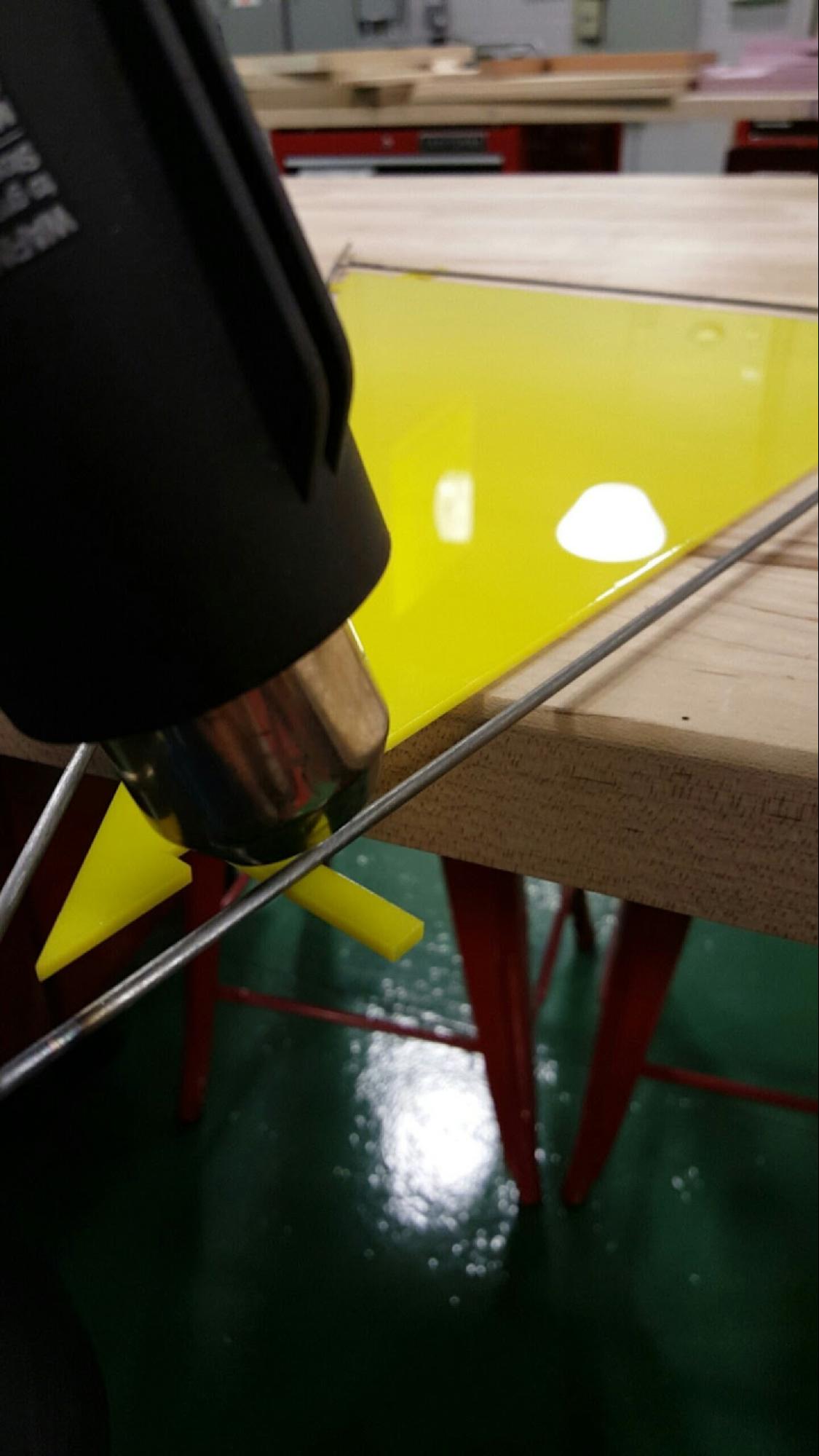
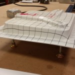
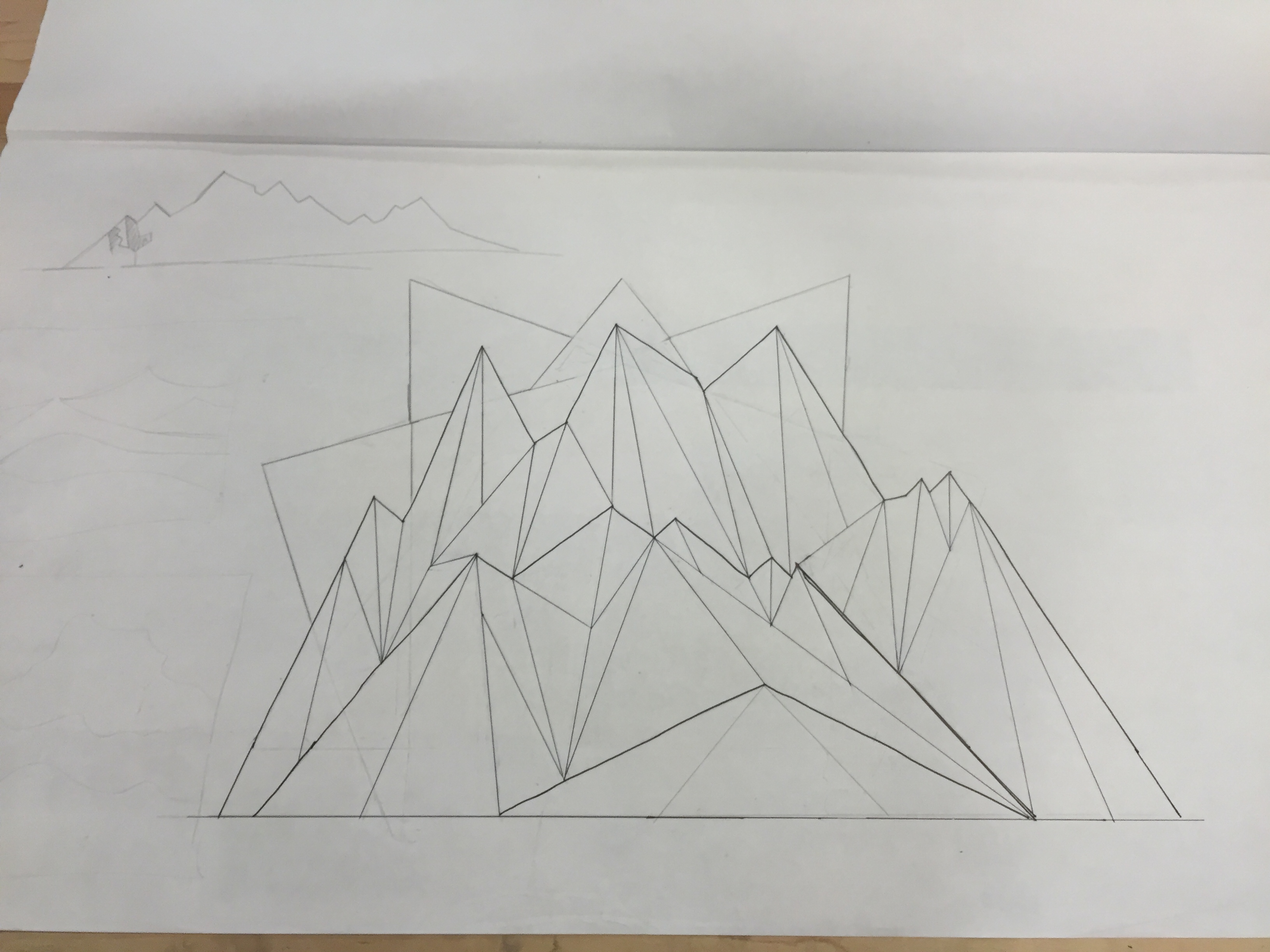
Next, I laser cut and bent acrylic over different parts of the design to give it a stained glass look.  To bend the acrylic I cut tabs out on the laser cutter and I used a heat gun to heat the tabs until they were flexible enough to bend. I would then bend it over the metal wire wearing gloves and would hold it in place until it cooled and solidified. To further the stained glass look I made a geometric design inspired by mountains and used puffy paint to paint it onto the acrylic. I then plan on filling in the different sections of the puffy painted design with glass stain so it has the appearance of stained glass.

Photo Aug 05, 10 16 29 AM        Photo Aug 05, 10 16 17 AM

Photo Aug 05, 11 51 54 AM         Photo Aug 05, 1 53 37 PM

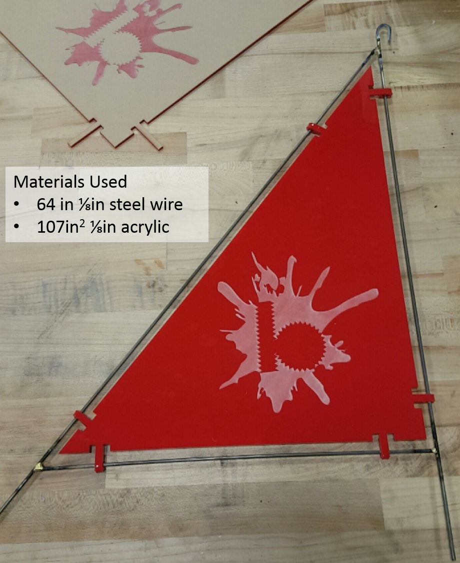
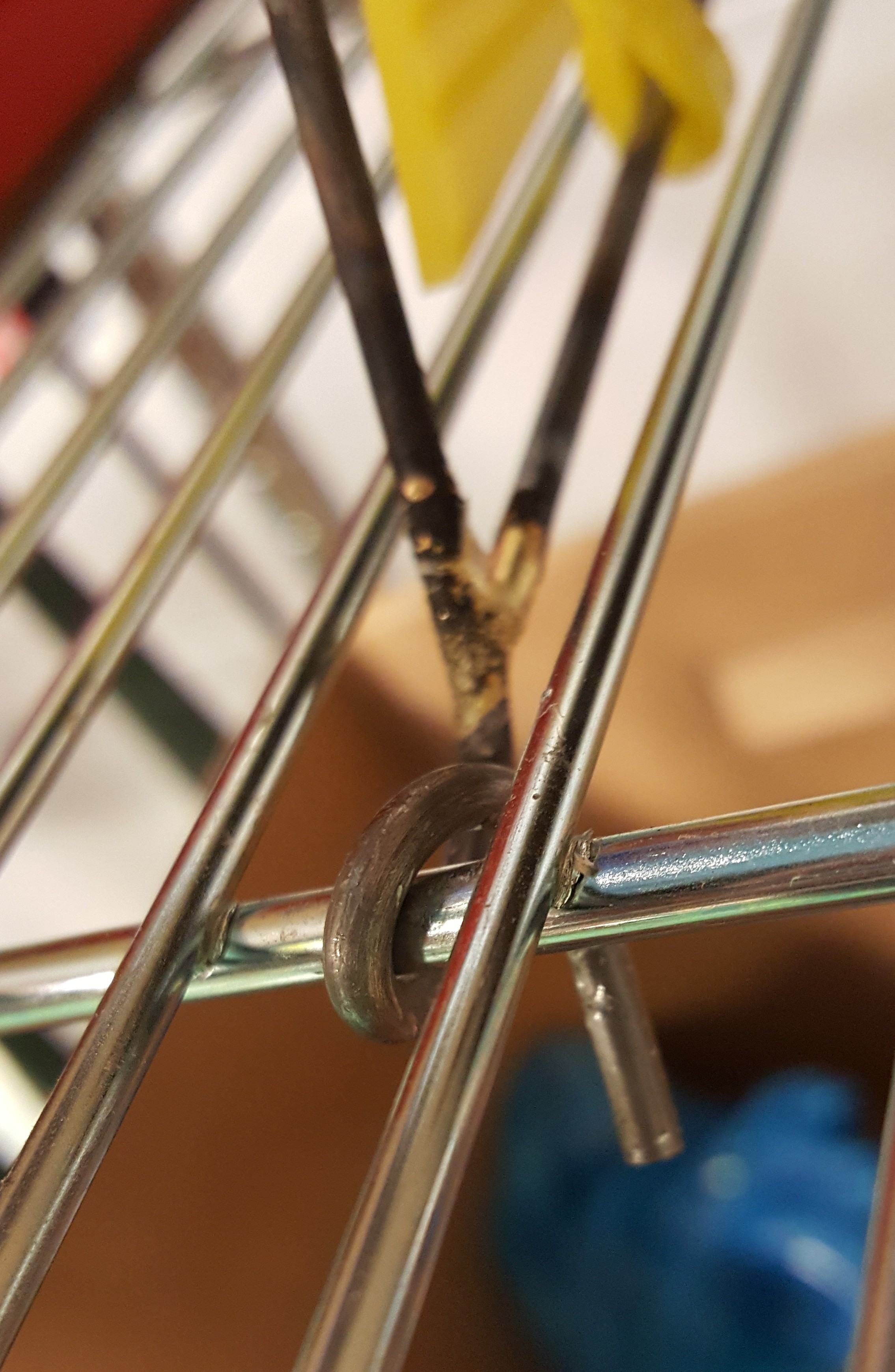
I was still debating how to attach the sides to the acrylic when my co-workers and I went on a field trip to Artisan’s Asylum. There I found inspiration for how to do just that. One of the artists who worked there had attached metal wires to a log by braising washers to the ends of the rods. This is what I then did to attach the sides of the stands to the top of the acrylic.

Photo Jul 25, 2 41 48 PM      Photo Aug 12, 12 26 56 PM

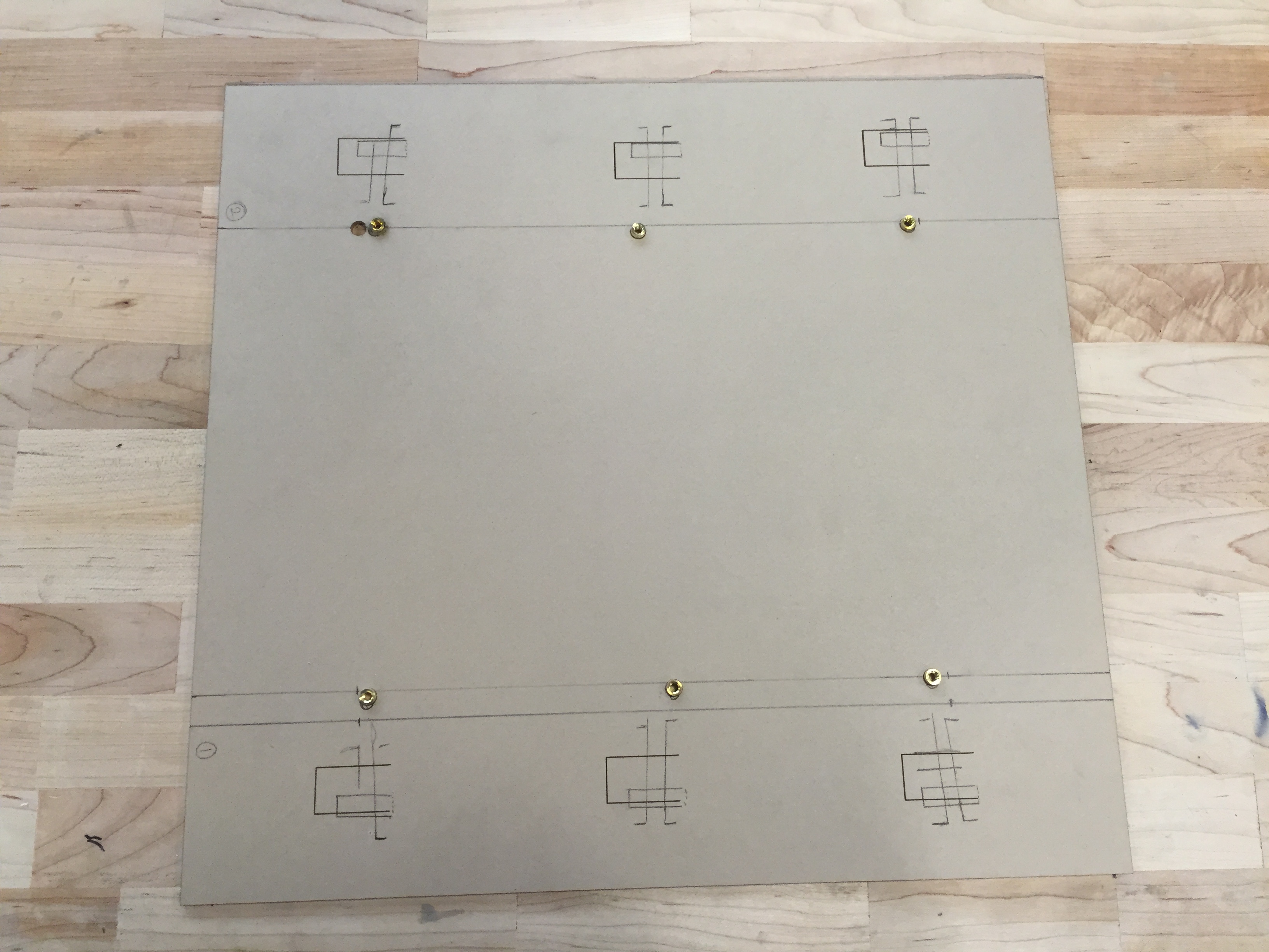
I laser cut holes into the acrylic and added threaded inserts using a soldering iron to heat up the insert and push it into the acrylic. This allowed me to screw the washers at the ends of the wires right into the acrylic top. I also laser cut more tabs into the acrylic and used the same method of acrylic bending that I used before to bend the tabs over the wires for extra support.

Photo Aug 12, 12 27 48 PM        Photo Aug 12, 12 27 19 PM            Photo Aug 12, 10 01 13 AM          Photo Aug 12, 2 18 39 PM

Finally I added a cross support across the back of the stand to give it more support and prevent it from wobbling. I braised the middle of the cross support to secure it in place. All I have to do now is paint the sides and the stand will be complete.

Photo Aug 12, 12 22 07 PM        Photo Aug 12, 2 18 32 PM

Shop Training Update: Final Picture Frame Design

After a long summer of brainstorming, ideating, prototyping, and revising, the picture frame is finally ready for deployment in the shop. Last week’s “wrap-up” frame design prompted the comment that most people print 4×6 pictures, not 5×7, leading to some quick dimension changes and the construction of a final prototype. This new frame holds 4×6 pictures snugly (a practical, appealing function), takes about 2 hours to make under ideal circumstances (commensurate with the wall hook), and lowers the cost by almost a dollar, down to $5.02 per frame (coverable by a small lab fee, as discussed in last week’s post).

IMG_3453IMG_3454


IMG_3455

As of now, the picture frame is officially a training option for those looking to use the yellow zone tools. All of this project’s goals were met successfully: the frame adds interest to the project, covers every tool in the yellow zone and incorporates some from outside, and is easily manufacturable by those new to the shop. With luck, these frames will soon grace shelves all across engineering dorm rooms at Tufts.

IMG_3458


Final Summer Update: Coffee Table

After spending the majority of the summer brainstorming, sketching, designing, modeling, and practicing the techniques required to build a table, we were able to assemble the final coffee table this week.

The first step in assembling the table was to mill the legs on the ShopBot. The way the legs were designed allowed me to run the same CNC program one time on each leg. To ensure that the program started and ended in the same place every time, I cut out a foam jig to clamp down on the ShopBot bed and then placed the leg in the jig.

One of the legs in the foam jig

One of the legs in the foam jig

Once the leg was done being milled, I was able to remove it without moving the jig, place a new leg in, and run the same program without having to re-zero any of the axes. I used a 1/4″ end mill bit to get a flat cut for the wrap to rest on.

Once Ben had completed the finger joints, we were able to put the table wrap together and fit the legs in. Unfortunately, some of the legs stuck out too far from under the wrap. The amount of material we needed to take away was too much for sandpaper or a hand planer, but too little for a table saw. Thankfully, there is a planing bit for the ShopBot (seen below).

Unlike the end mill and ball nose mills, the planing bit cannot plunge

Unlike the end mill and ball nose mills, the planing bit cannot plunge

Having only used that bit once with HDPE, I was reluctant, but it was looking like our best option. I placed my legs back into the foam jig I used earlier, switched out the 1/4″ end mill bit for the planing bit, and used a .1″ pocket cut on two faces of each leg.

One of the table legs being planed

One of the table legs being planed

Once the wrap fit on the legs, I moved on to milling the model of Tufts. The pieces of plywood I was using were 22-1/2″ x 17-3/16″ x 1-1/2″, which is just about the size of the ShopBot bed (which is 24″ x 18″). This left very little room to put any clamps on, let alone enough clamps to make sure the piece wasn’t going to move while it was being milled. The few clamps I could get on were difficult to hold down as the knobs were too wide in diameter and kept hitting the sides of the stock piece. I decided to design a corner clamp (seen below) that would keep my piece square, straight in the X and Y directions, and have enough room to use the knobs without getting in the way of the material or the bit.

Corner clamp

Corner clamp

I 3D-printed the clamps so that in case they did get in the way of the bit, they wouldn’t damage the bit and could easily be re-printed. I did one final, to-scale model of the Tufts map in foam with the 1/” end mill bit before I used the plywood. The foam model turned out just as expected.

The practice foam being milled

The practice foam being milled

I left the clamps in the same position, and just switched out the foam for the plywood, and ran the same program.

The plywood being milled for the final model

The plywood being milled for the final model

I repeated that process with the rest of the map sections to produce the base layer of the map.

Coffee table with the base layer of the model in place

Coffee table with the base layer of the model in place

The two top layers are currently being milled and will be added to the table shortly. The rest of the table has been stained and is about ready to be moved to it’s final destination in the Design Lab!


Implementing the Rack Dividers

Purpose: One of the goals for this summer at Bray was to find a way to help organize the material in the machine shop. We noticed the rack near the laser cutter held three disorderly piles of acrylic which were difficult to sift through to find the right piece. To fix this, we decided to create rack dividers that would show off some the of what can be done in the shop.


set


Design: Considering the rack was our environment, we came up with a divider that could easily clip into the rungs on the rack. Wanting at least three points of connection as well as geometric sturdiness, we decided to make steel framed triangular dividers. The process for making these involved four steps: cutting and brazing the wires, laser cutting and etching the acrylic, heating bending the acrylic into the steel frame, and joining the divider into the rack itself.


materials

Major Resources Used


Step 1: Cutting & Brazing

The frame consisted of three wires, 14″, 24″, and a 25.5″.  After cutting the wire ends are sharp and must be deburred with a file. After bending 1 inch of the 24” over to make a loop, the last step before brazing is to sandpaper off the steel coating at the binding joints.

Brazing Components

Brazing Components

Brazed joint

Brazing is the process of binding two pieces metal with brass filler by torch. The three steel pieces are brazed to be connected as shown below. Proper brazing training is required to assemble.

sketch


Step 2: Laser Cutting and Etching

An acrylic plate is laser cut to internally fit the steel frame. We etched an aesthetic Bray logo on the side as well. The tabs will wrap around the steel frame by a process known as heat bending.

T drawing

Step 3: Acrylic Heat Bending

Each of the six tabs are heated with a heat gun and bent around the wire, cooling and settling in a securing and binding form to the steel frame. This process has been used in at least one other summer project and shows promise as a useful skill for creating sturdy and functional plates.

Heat Gun Applied to Acrylic Tabs

Heat Gun Applied to Acrylic Tabs


Step 4: Installing the Dividers

The dividers should have extensions past all three endpoints. The first one is the hook made earlier. Installing the dividers starts with appropriately placing this hook and the rest of the body into the desired location on the rack.

20160811_091233

Initial Top Hook

Next, the bottom two extensions need to be bent to secure in the divider. This was done by a set of slip joint pliers, groove joint pliers, and long nose locking pliers. The coil (below) around the front was difficult to obtain since there were very bad angles for most of the turns and the steel is tougher then the rack material itself.

20160811_091220

Front Coil

Final Result

20160811_091040

Aesthetically Pleasing and Efficient Use of Space


Holds Significant Quantity of Acrylic. Organized by Sheet Thickness and Size

Further: These racks were  successful in design and implementation. Since the dividers are close, they can hold more acrylic by lowering the horizontal force while leaning. Different acrylic inventory in the future can also be accounted for by moving which type of material is where. There are also plans for creating modular labels are on the way and which will further ease the trouble of finding just the right sheet to make your laser cut.

More of these can be made on the other shelf (or another rack!) to help store foam and wood material in the shop. The design of these dividers were made in such a way that they could be modified for other racks or spaces to help organize. If another iteration of these dividers are made, we suggest changing the reliefs to be more rounded in order to distribute pressure along the tabs’ bases. Also, if any of these dividers break, it should be easy to clip that divider out and install a new one by the same method outlined above.


Shop Training Update: Wrapping up the Picture Frame

After a third prototype and some experiments with acrylic forming, the picture frame is, I believe, nearing completion. This prototype, shown below, goes for more of a “polished-industrial” feel that hides a larger purpose: the cap nuts securing the vertical frames to the acrylic plate allow for zero-tools insertion of a picture, something that was not possible in the previous two designs and could preclude many students from using their frames.

frame_rev03_exploded IMG_3395

Compared to the wall hook, this frame has several key advantages that I believe make it an ideal shop training project, either as a supplement to the hook or as a complete replacement.

  • Scope: The wall hook required only three yellow zone tools: the horizontal bandsaw, the drill press, and the jump shears. Students used the vertical bandsaw for a single cut, but with the caveat that they weren’t really supposed to use it for what they were doing—an odd thing to say during shop training. The picture frame, by contrast, requires five yellow zone tools, incorporating the hand drill and laser cutter into the original three. Additionally, the plate stock, while cut entirely on the jump shears for the prototype, could be cut properly on the vertical bandsaw with no caveats, thus making for six tools used properly.
  • Variable tool usage: Of the wall hook’s 31 required power tool operations, a whopping 26 of them (84%) took place on one of the shop’s three drill presses. This high percentage of drilling and countersinking operations created major bottlenecks when large numbers of students were trained at once. The picture frame spreads out the tool usage much better, with only 18 of its 32 operations (56%) taking place on the drill press. The plate work on the supports could be split evenly between the jump shears and vertical band saw, reducing bottlenecks even further. The only real potential for a major bottleneck is at the laser cutter, but I believe efficient management of it so that multiple students are trained and cutting their single part at the same time could make its use manageable.
  • Variable parts: The wall hook’s five pieces were all very similar (or, in two cases, exactly the same), each requiring almost the same order of operations. By contrast, each of the picture frame’s three unique components (two components are mirror images) requires a completely different set of skills from the others: the acrylic backing plate is laser-cut; the bar stock frames are cut on the horizontal bandsaw and drilled on the drill press; and the plate supports are cut on the jump shears or vertical bandsaw, hand-drilled, and countersunk on the drill press. And because the drill presses are split, two for drilling and one for countersinking, there is no tool usage overlap between parts as there was with the wall hook. If there is a line at the drill press, those not in line can work on a part that does not require the drill press, something that was not possible with the wall hook.
  • Less tapping: The picture frame has half as many tapped holes as the wall hook, giving students the opportunity to get a feel for the process but giving them fewer chances to break a tap.
  • Interest level: The wall hook perhaps received the most grief because of its lack of utility in a college dorm. Because the dorms forbid screwing into walls, most students could not make use of their hooks, leading to a lack of interest from those students who were not interested in the act of making something. The picture frame, requiring no mounting, presents a desirable end goal for those more results-driven than process-driven.

All of these advantages together, I believe, outweigh the one major disadvantage the picture frame presents: cost. Considering only the cost of materials in the finished product—that is, not accounting for students breaking taps, remaking parts, etc.—the frame costs $5.96, compared with the wall hook’s mere $0.74 price tag. I would argue, however, that the expanded scope and heightened interest level present a compelling case for adopting the picture frame and adding a small lab fee to the course. I believe most Tufts students would be fine paying a small price for a more useful end product; furthermore, it is almost expected in other disciplines here that courses with lab components are going to have a lab fee. For biology or chemistry, these fees can reach into the hundreds of dollars; by contrast, a $5 or $10 fee would seem insignificant, especially if it is clear that it pays for a concrete end product.

Several prospective students on a tour were asked about shop training projects, and while they thought the wall hook was decent and liked the pen holder more, they all agreed that the picture frame held the most appeal for them. I think many students would feel the same, given the choice between something they cannot really use and something that they may already want. And the more concrete advantages only add benefits.

IMG_3402


Shop Training Project Redesign – Penholder Completed

The final edition of the penholder has been completed and nearly approved for commission as one of the shop training projects. In this most likely final blog post, we would like to do a brief review of the purpose of the project as well as go over a further inspection of the penholder and discuss the final outcome.

Purpose

To review, the penholder project concept was birthed as a way to give students more options for fabricating a project that gives them appropriate training with the shop’s power tools. We figured that a project is the best way for students to be trained, but we realized that there were some complaints with the old project, which was a wall hook. The wall hook was impractical as it had to be drilled into a wall for usage. However, drilling in dorm walls goes against residential life policy at Tufts. In addition, the project was also relatively dull and it also existed as the only option available for power tool certification. Therefore, we brainstormed ideas for new project ideas that were practical, creative, but also didn’t sacrifice using all of the power tool equipment, override the budget, and take too much time. Thus, the penholder idea was born.

The final penholder CAD design is shown below:

Final assembly drawing JPG


Build Process

Naturally, it is important to describe the details of the fabrication process.  The project incorporated the use of every power tool in the yellow zone of the shop. Therefore, we succeeded in our main objective – giving students adequate training in all tools. In terms of a time estimate, we didn’t keep a sturdy time count, but it was estimated the project would take about 4 hours to complete. It is also important to recognize time for errors and miscalculations, which are important as part of the learning process. Therefore, the project is a quite a bit long, but not too long to dismay students, we think.

penholder final

Tool Usage Diagram

Further inspection: hindrances and benefits

Picture4

We certainly like the design and practicality of the penholder. However, one aspect that gave us some trouble was the number of holes needed for the design. If we had more time to develop a better design, we would try to brainstorm a way to reduce the number on the top support; an attempt is shown below but would not securely fasten the arms with only one hole. Hole reduction would save time needed to fabricate, as well as decreasing the chance of having to redo the most intricate piece. Additionally, the penholder used more material and cost about 2.8x the wall hook.

IMG_3390

Previous penholder design

An appealing aspect of the penholder is that there is slightly more margin of tolerance than the wall hook. Since the wall hook worked with such small pieces, it was incredibly easy to make a small error, but small errors would also be overwhelmingly apparent. Since the penholder involves working with bigger pieces, errors can definitely still be noticed, but there is slightly more room for lesser mistakes without affecting its aesthetic or functionality; this is important because most people will be able to make a functional device. We noticed that many people would complete the wall hook and they would look quite crooked and in some cases, unusable. We hope that people will still make mistakes so they can learn, but also be happy with their object at the end of fabrication.

Additionally, it may be worth mentioning that we polled some incoming freshmen about which design they prefer if they had to fabricate a project. We showed them the completed penholder and wall hook and the majority preferred the penholder. Since this was such a small sample size, it doesn’t capture the entire sentiment and tendencies of the student body’s preferences, but we just thought it their preference was reassuring. Also, it is important to understand that the wall hook will still remain a viable project for students to create for their training. They will now just have the option to do either the wall hook, penholder, or picture frame (which will be discussed in a separate blog post).

We have submitted our drawings for final review by the fabrication supervisor. We are excited that the design will hopefully be approved and ready for fabrication by students in the upcoming semester.


Other Media


Picture5

Part Specifications


20160803_135502

20160803_135311


Summer Update: Coffee Table

This week we moved away from modeling the table with foam, and began working with the wood that we will use to build the final table. At the beginning of the week I continued to practice making finger joints by hand, using a Japanese Z saw, chisels, and a mallet.

The finger joints will connect all side of the table wrap.

The finger joints will connect all sides of the table wrap

Yesterday, we went to Home Depot and back to Nedlam’s Workshop at Malden High School to prepare the wood for the final table. First, we used the jointer to make sure all of the wood was flat and square before we made any exact measurements or cuts.

Using the jointer at Nedlam's Workshop

Using the jointer at Nedlam’s Workshop

Next, we measured the final widths of our boards and drew up some sketches to plan out how to cut the rest of the wood.

Final measurements for the table wrap

Final measurements for the table wrap

With our measurements planned out, we began by cutting all of the wood to the correct width using the table saw. First, we cut the legs of the table, then we cut our side boards. Once the wood was cut to the proper width, we set up the table saw with dado blades. These blades can be stacked together (shown below, right) to produce a thicker cut than the width of just one blade.

http://www.toolstoday.com/images/dado-Saw-Blades-header.jpg

http://www.toolstoday.com/images/dado-Saw-Blades-header.jpg

With the dado blades in place, we cut channels in each of the boards that the plywood base will sit in once the wrap is assembled. Once the channels were made, we used the miter saw to cut our boards down to the correct length.

Mickey helped us set up the dado blades and cut the channels

Mickey helped us set up the dado blades and cut the channels

When we returned to Bray, it was time to glue our plywood together and prepare the MDF legs for milling practice. Once we test the Vcarve files on the MDF legs, we can mill the actual legs.

MDF legs clamped down while drying

MDF legs clamped down while drying


Next, we will be making the finger joints on our eucalyptus boards to create the table wrap, milling the topography out of plywood, and assembling the table!

Field Trip: WIT, MassART and MFA

Wentworth Institute of Technology

The Bray Lab staff and summer interns visited the Center for Applied Research at Wentworth Institute of Technology in their Department of Architecture. The Center supports bachelors (sophomore year and above) and masters students in Architecture – around 450 students.


Vacuum Forming Process at WIT

The newest edition to the Center – Kuka Robotic Arm


MassART

Lee MacDonald, Studio Manager at MassART gave us a tour of some of the fabrication spaces at MassART.


MFA

Finally, we wrapped up our field trip with a visit to the Museum of Fine Art which offers free admission for Tufts students.

Below is a picture of how Charles and Ray Eames applied the methods they used for designing and making furniture to creating mass-producible leg braces during World War II:

20160801_153407

Group photo in the Japanese Garden:

20160801_160918


Summer 2016: Othermill Reference Pages

Over the past weeks, I have been working to set up tutorial and reference pages on how to use the Othermill for 2D and 3D pieces. I included information I found on the Othermill support page, other online tutorials, and tips and tricks I found to be useful from my own experience with the machine.

2D Work

This tutorial goes over both the basics of the Othermill and its physical set up, as well as how to use use the relevant pieces of software. By walking through the set up of a sample file, users are reminded of how to properly format it. The tutorial progresses from a pre-made design in illustrator, to the properly formatted file, explains how to set it up using the Otherplan software, and finally describes the steps necessary for the physical set up. Although it is thorough, the tutorial should not be used to learn how to use the tool. Instead, it should be used for students to reference for help after the trainings. Below is an example of what can be done using the 2D capabilities of the Othermill:

Screen Shot 2016-08-03 at 12.06.08 PM

Simple 2D file created in illustrator to create a wooden coat hook

Photo Aug 03, 11 29 13

Solid wood coat hook milled using the Othermill

3D Work

The 3D tutorial page does not cover as much of the Othermill basics. Since the physical set up is very similar, it assumes that the user would already have a firm grasp on how to use the tool. Instead, it focuses on converting a model into code that the Othermill can understand. To achieve this, I used Fusion 360. It is an extremely powerful CAD software with a CAM environment. Due to the the vast capabilities of the software, the tutorial had to be quite extensive and detailed. I included some screen shots of the more complicated menus along with appropriate labels. I would advise against using this tutorial as a singular resource to learn how to create 3D topographies using the Othermill. Much like the 2D, it is intended to be a reminder of what was taught during trainings. Below is a sample piece that was made using the 3D capabilities of the Othermill:

Screen Shot 2016-08-03 at 11.58.26 AM

CAD model of piece to be milled

Photo Aug 03, 10 16 08

Final 3D piece created using the Othermill

« Older posts

© 2024 Bray Lab

Theme by Anders NorenUp ↑