Purpose: One of the goals for this summer at Bray was to find a way to help organize the material in the machine shop. We noticed the rack near the laser cutter held three disorderly piles of acrylic which were difficult to sift through to find the right piece. To fix this, we decided to create rack dividers that would show off some the of what can be done in the shop.
Design: Considering the rack was our environment, we came up with a divider that could easily clip into the rungs on the rack. Wanting at least three points of connection as well as geometric sturdiness, we decided to make steel framed triangular dividers. The process for making these involved four steps: cutting and brazing the wires, laser cutting and etching the acrylic, heating bending the acrylic into the steel frame, and joining the divider into the rack itself.
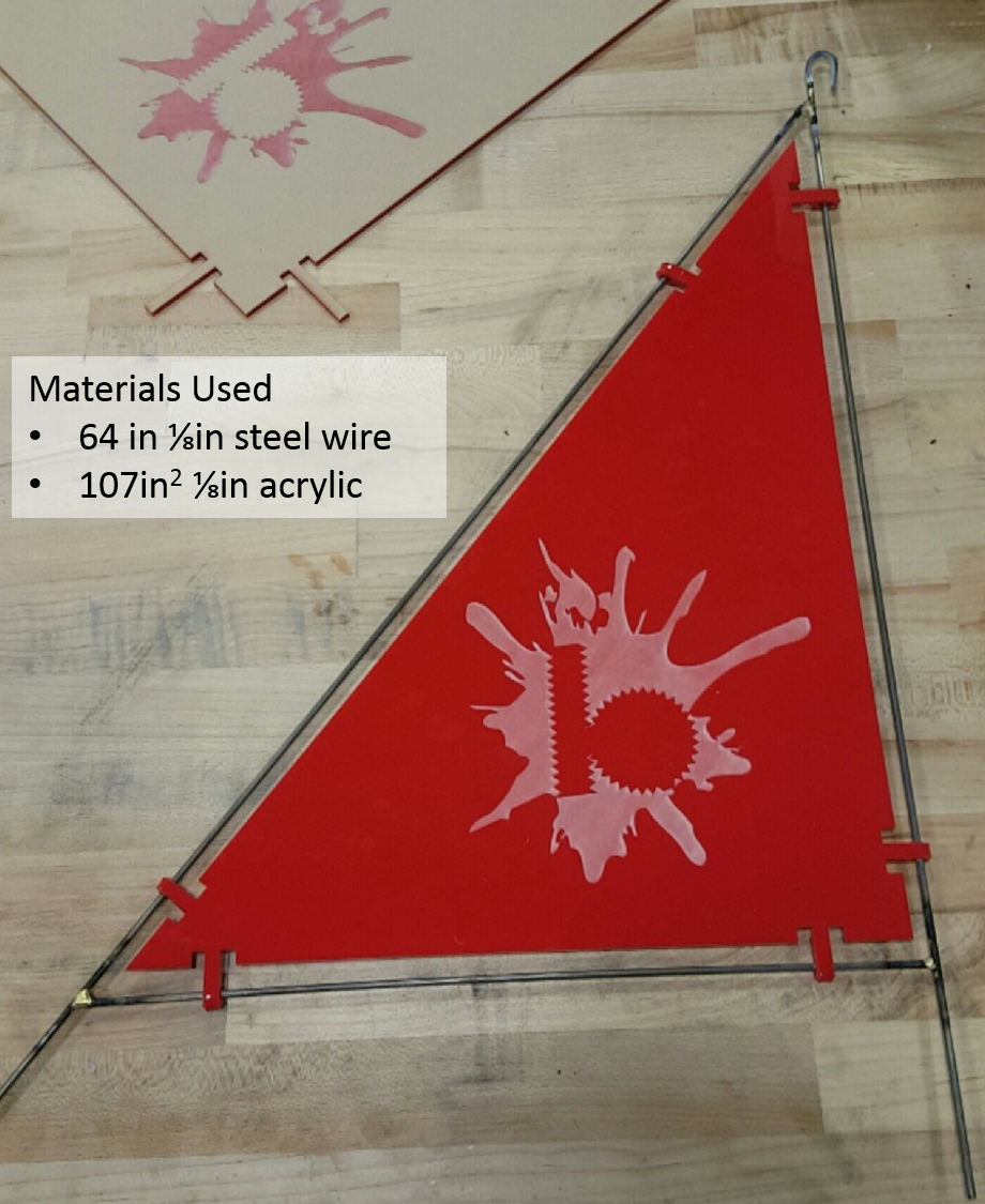
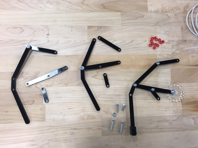
Major Resources Used
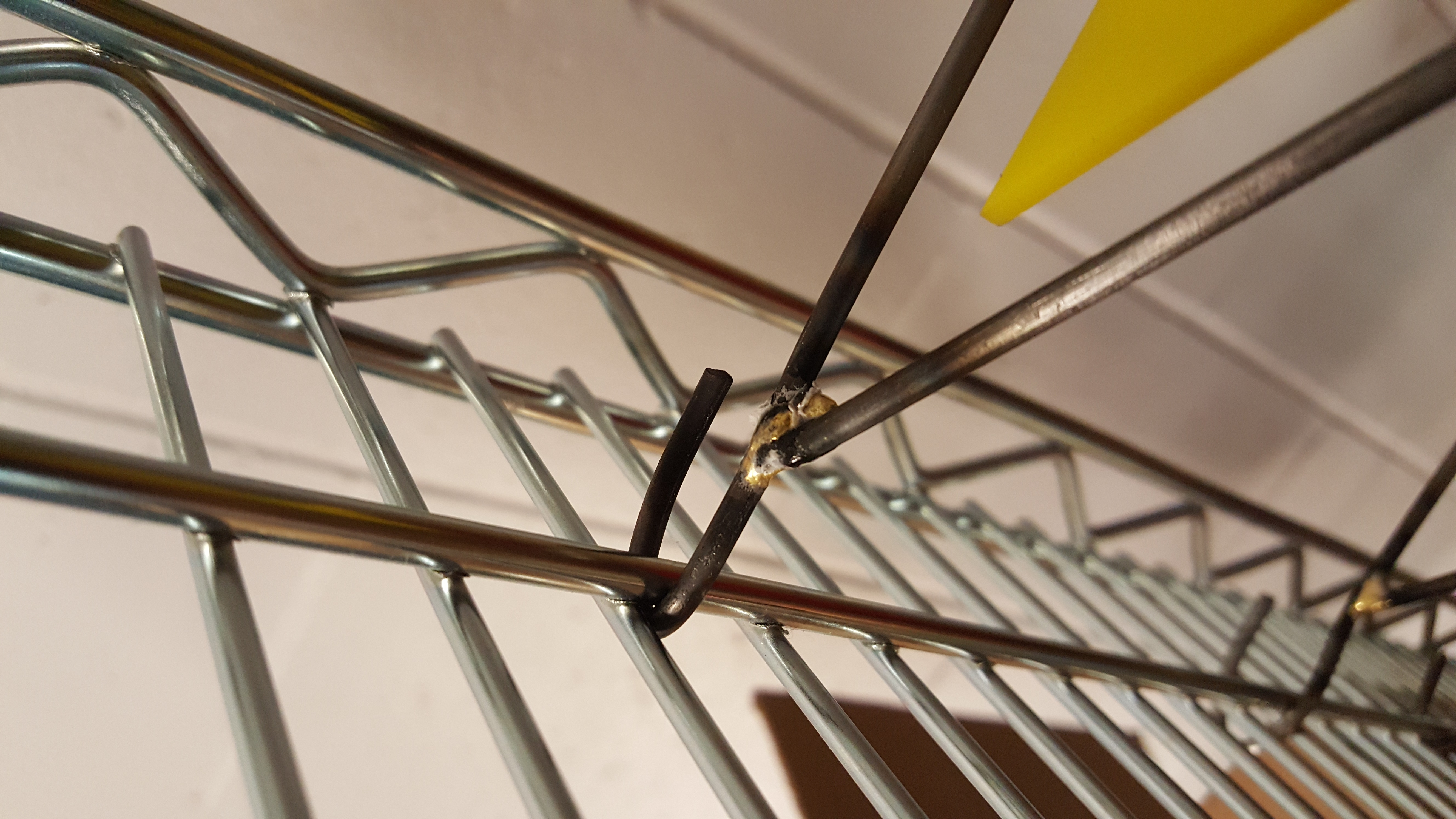
Step 1: Cutting & Brazing
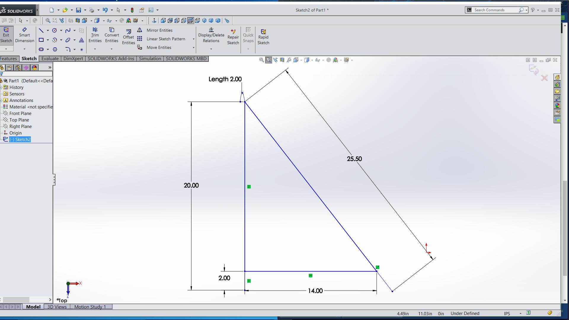
The frame consisted of three wires, 14″, 24″, and a 25.5″. After cutting the wire ends are sharp and must be deburred with a file. After bending 1 inch of the 24” over to make a loop, the last step before brazing is to sandpaper off the steel coating at the binding joints.
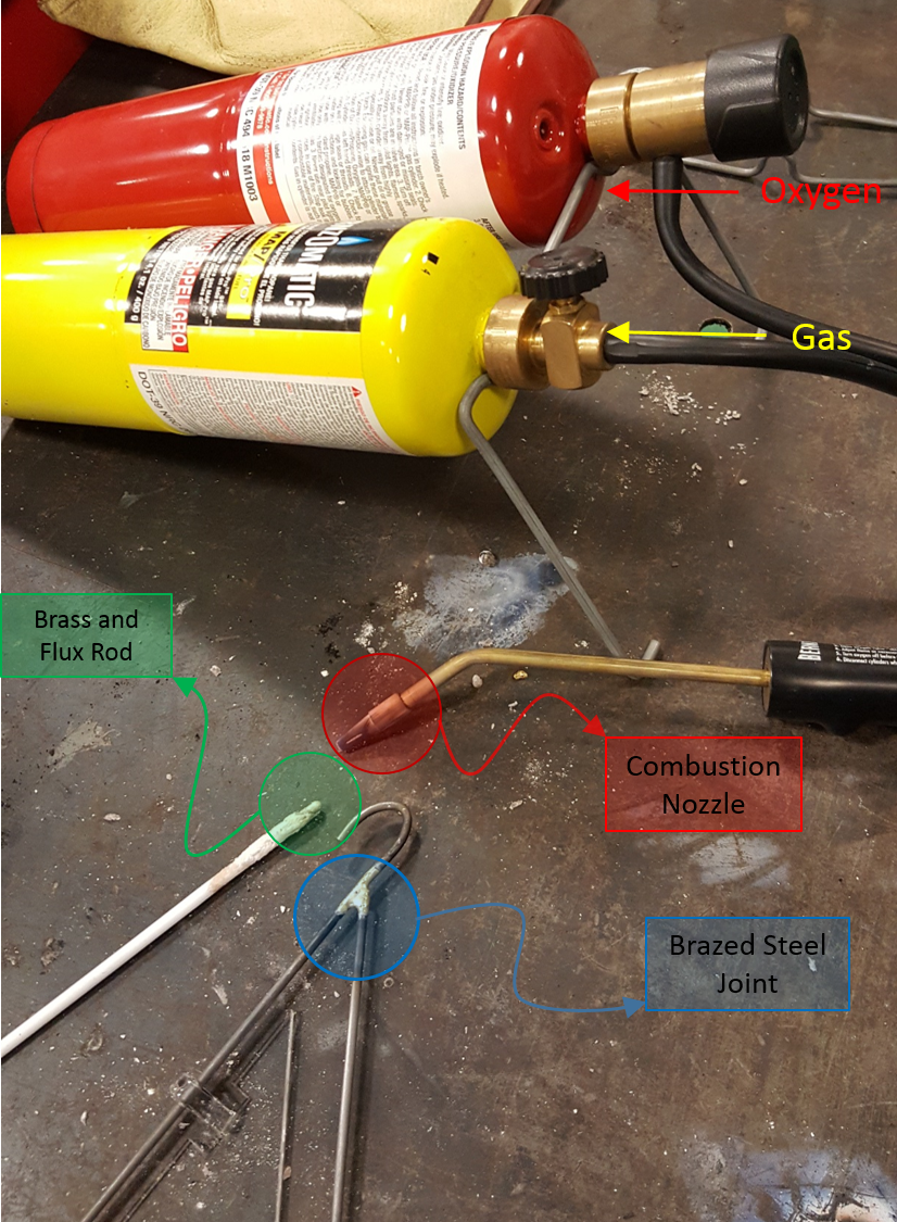
Brazing Components
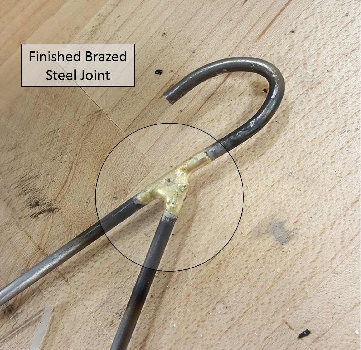
Brazing is the process of binding two pieces metal with brass filler by torch. The three steel pieces are brazed to be connected as shown below. Proper brazing training is required to assemble.
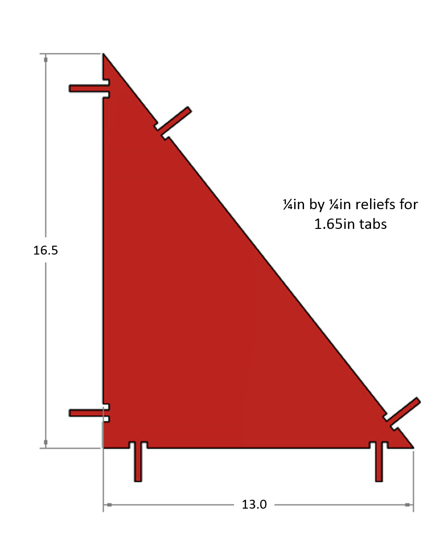
Step 2: Laser Cutting and Etching
An acrylic plate is laser cut to internally fit the steel frame. We etched an aesthetic Bray logo on the side as well. The tabs will wrap around the steel frame by a process known as heat bending.
Step 3: Acrylic Heat Bending
Each of the six tabs are heated with a heat gun and bent around the wire, cooling and settling in a securing and binding form to the steel frame. This process has been used in at least one other summer project and shows promise as a useful skill for creating sturdy and functional plates.
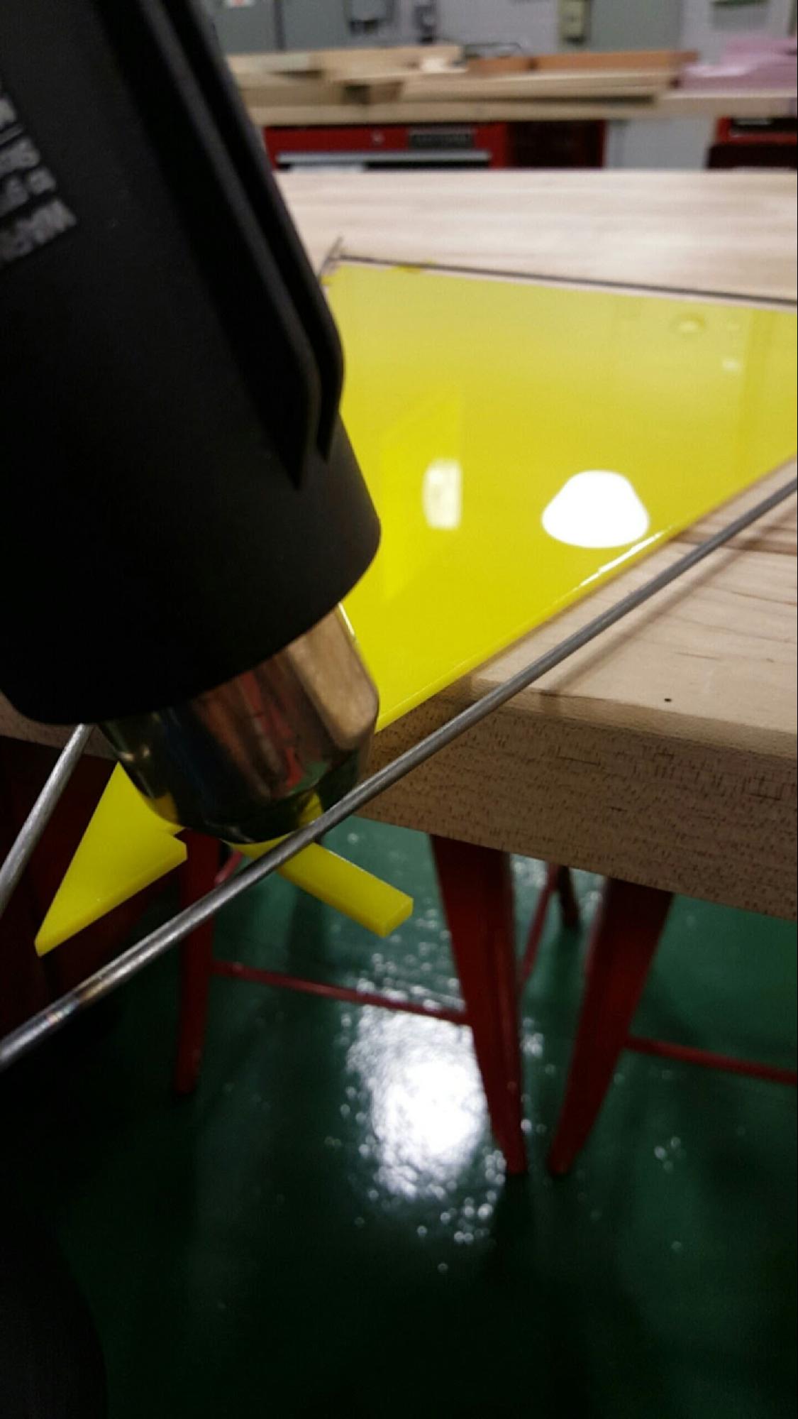
Heat Gun Applied to Acrylic Tabs
Step 4: Installing the Dividers
The dividers should have extensions past all three endpoints. The first one is the hook made earlier. Installing the dividers starts with appropriately placing this hook and the rest of the body into the desired location on the rack.
Initial Top Hook
Next, the bottom two extensions need to be bent to secure in the divider. This was done by a set of slip joint pliers, groove joint pliers, and long nose locking pliers. The coil (below) around the front was difficult to obtain since there were very bad angles for most of the turns and the steel is tougher then the rack material itself.
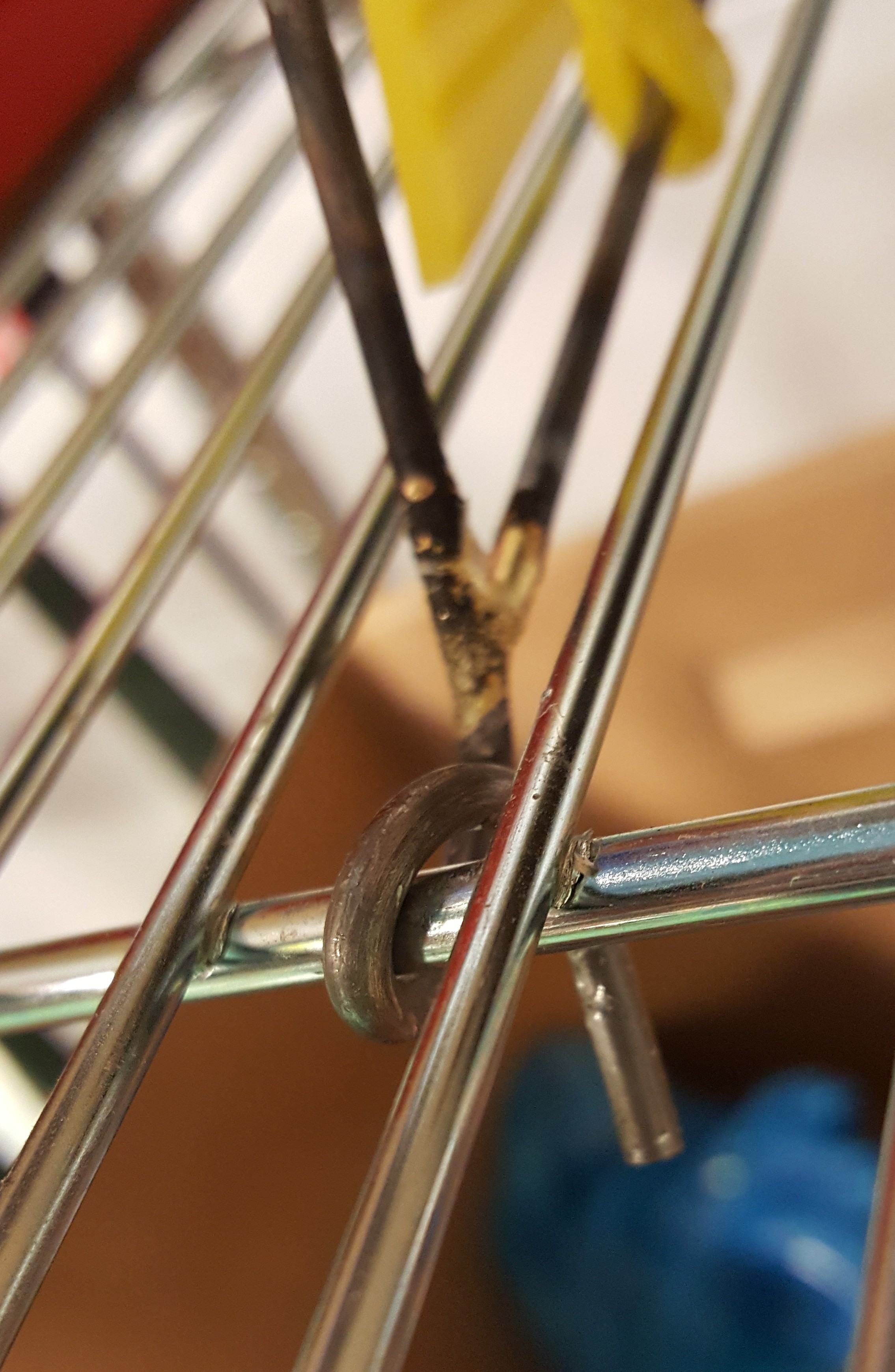
Front Coil
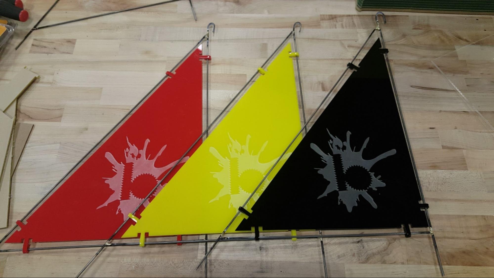
Final Result
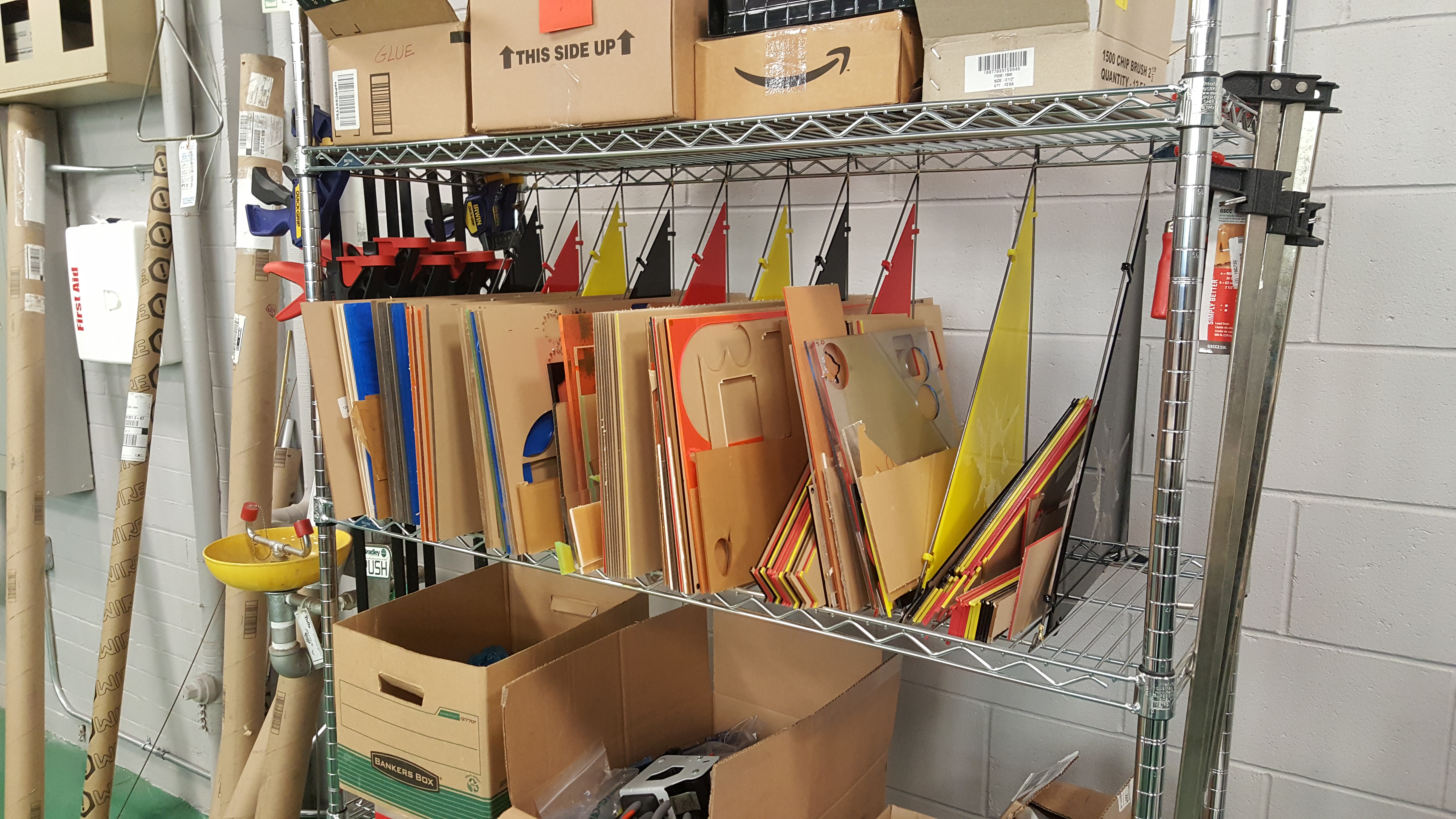
Aesthetically Pleasing and Efficient Use of Space
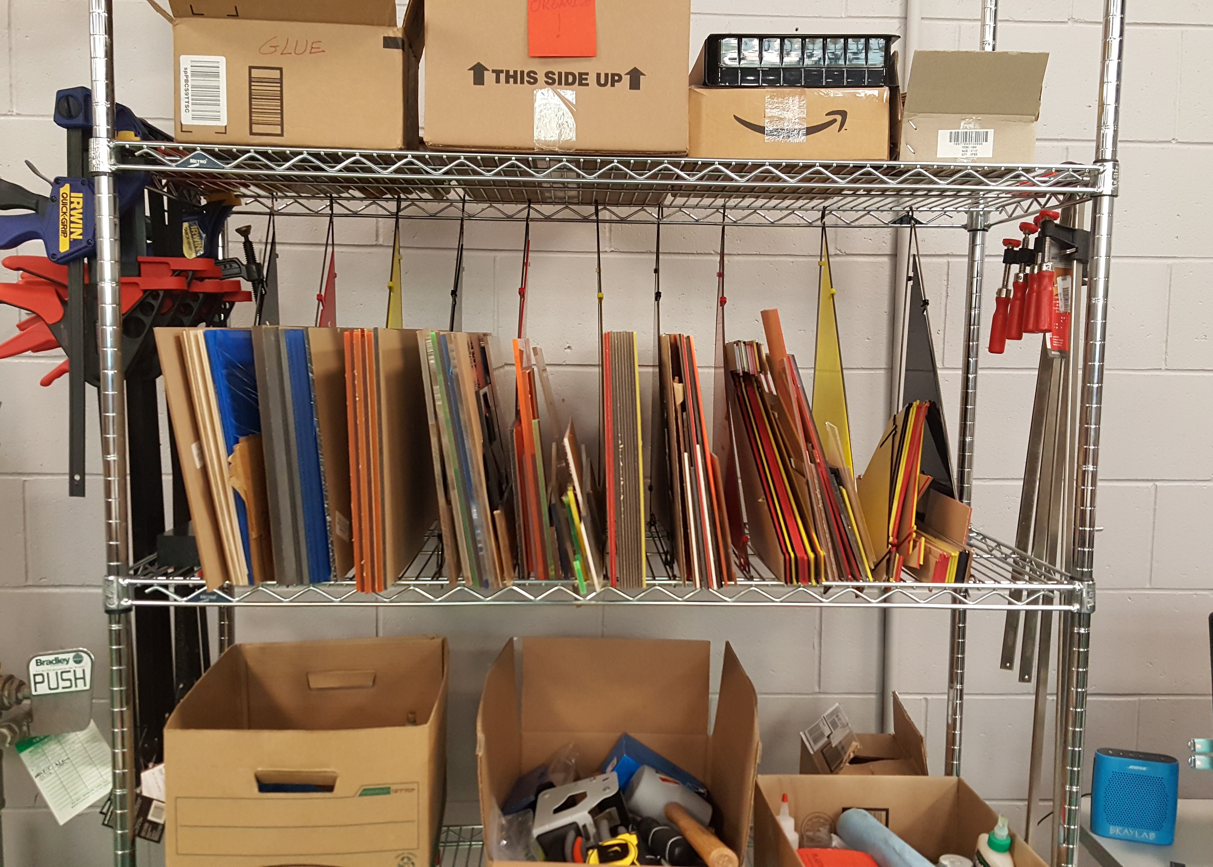
Holds Significant Quantity of Acrylic. Organized by Sheet Thickness and Size
Further: These racks were successful in design and implementation. Since the dividers are close, they can hold more acrylic by lowering the horizontal force while leaning. Different acrylic inventory in the future can also be accounted for by moving which type of material is where. There are also plans for creating modular labels are on the way and which will further ease the trouble of finding just the right sheet to make your laser cut.
More of these can be made on the other shelf (or another rack!) to help store foam and wood material in the shop. The design of these dividers were made in such a way that they could be modified for other racks or spaces to help organize. If another iteration of these dividers are made, we suggest changing the reliefs to be more rounded in order to distribute pressure along the tabs’ bases. Also, if any of these dividers break, it should be easy to clip that divider out and install a new one by the same method outlined above.