Category: Summer Internship 2016 (Page 2 of 4)

Shop Redesign – Penholder

We have finished modeling the Penholder after several iterations and have fabricated a working prototype.

Assem1

Assembly of penholder prototype 1.1


Photos of the built prototype:

IMG_3387IMG_3388

IMG_3390

IMG_3391

IMG_3392


Drawings of individual Penholder parts

Penholder Baseplate

penholder-baseplate draw


 Penholder Arm Support

penholder-arm draw

Penholder Top Support

penholder-topsupport draw


Penholder Main Support
penholder-mainsupport draw


The Penholder successfully holds pens! It has the same number of tap drills as the wall hook but uses more half by quarter inch material and sixteen inch sheet metal.


Shop Training update: picture frame

This week saw great leaps forward on the picture frame, but ultimately proved something of a disappointment. The great leaps: a new design and two prototypes! The drawings showcased in last week’s post were prototyped, resulting in a proof-of-concept model that actually worked fairly well.IMG_3381

This design did turn out to have some issues, however. Most notably, it proved much more difficult than anticipated to accurately bend the frame’s aluminum legs; additionally, the bending process slightly warped the frame’s center sheet, preventing the picture from laying flat.

These considerations—difficulty bending and a warped image support—led to picture frame, rev. B, the designs for which are shown below. It replaces the single bent aluminum sheet frame with two aluminum sheet legs that are screwed into the vertical picture clamps, with the picture backed by a 1/8″ acrylic sheet.

frame_drawings_rev02_p1 frame_drawings_rev02_p2 frame_drawings_rev02_p3 frame_drawings_rev02_p4

As this design did not include any sheet bending, it proved much easier to build using only the tools currently in the yellow zone than the initial design. This new design was prototyped as well:

IMG_3382

As suspected, the new design proved much simpler to build. However, I still believe it fails on two counts. First, it incorporates two tools that are not used in the wall hook: the laser cutter (to cut the acrylic), and the hand drill (to drill the holes in the leg plates). Second, and more important, this design costs over $7 in raw materials, several cents more than the initial design and far more than the $0.50 wall hook. As such, if we were to proceed with this design, we might need to incorporate a “pay-to-play” model, where the wall hook is the default option, but students can pay a materials fee to make something larger.


Summer Update: Coffee Table

This week was focused on modeling the coffee table with various practice materials to get an idea of what parts of the building process might be tricky, practice joinery techniques, and  finalize design elements.

Originally, the legs were going to sit on the outside of the table, with the sides of the table resting on them (seen below, far left)

Evolution of table leg design

Evolution of table leg design

After practicing with the XPS foam (shown below), we redesigned the leg several times before deciding on a final plan (above, far right). Now, the sides of the table will sit on the outside of the legs.

Examples of the leg with  slots instead of round holes

Examples of the leg with slots

Instead of trying to create perfect right angles on the CNC Router for the side or reinforcement pieces to fit in, the head of the leg will be cut on the CNC and then two holes will be drilled on both sides for wooden dowels.

Yesterday, I took the practice wood to Nedlam’s Workshop at Malden High School to  plane it before we started building.

Planing the wood at Nedlam's Workshop

Using the jointer at Nedlam’s Workshop

Next, I began practicing making finger joints with scrap wood. The joints will connect all four sides of the table.

Untitled-1

Throughout next week I will continue to practice the necessary woodworking techniques, finish building the practice table, and plan out the construction of the final coffee table!

Field Trip: Artisan’s Asylum

This week the Bray Lab staff and summer interns visited Artisan’s Asylum, a non-profit community fabrication center in a 40,000 square foot warehouse located in Somerville.

Artisan's Asylum


We got a chance to checkout the setup of their equipment stations:

Artisan's Asylum - Soldering Station

Artisan’s Asylum – Soldering Station

Artisan's Asylum - Jewelry Station

Artisan’s Asylum – Jewelry Station

Artisan's Asylum - Casting Room

Artisan’s Asylum – Casting Room

as well as their storage methods:

Artisan’s Asylum – Vertical Storage


We met the Overhaul robot featured in BattleBots and spoke with one of its makers.

Artisan's Asylum - BattleBots

Artisan’s Asylum – Overhaul BattleBot


We checked out some of the builds to gain inspiration for projects in Bray.

Artisan’s Asylum – Coffee Table


3D Printer Repair

Lately, one of the 3D printers in the Design Lab has been acting improperly. Upon extrusion, the filament would not come out straight from the driver. Instead, the material would bend upwards, often times catching itself on the extruder or creating clumps and knots in the filament that wouldn’t stick to the bed.


We originally thought that there was a clog in the extruder screw tip, so our first goal was to replace it. Also, the extruder was covered in plastic and was missing some insulation tape, so we figured that melted plastic was interfering with the path of the filament or that the tip wasn’t heating properly which would impact the state of the material as it extrudes. Either way, we thought that if we replaced the screw tip, cleaned up the melted PLA, and added more tape, the 3D printer would revert to extruding properly. We began this process by removing the extruder from the conveyor track and preheating it so we could chip away the melted plastic. Once the driver was cleaned up we completely took apart the extruder and examined it for any issues but couldn’t find any obvious problems. From there, we removed the screw tip, which was much harder than expected. We then removed the old tape bits and added a fresh layer of tape and reassembled the extruder. However, when we tried printing, the same problem would occur.

We decided to take apart the extruder once again to look for problems with the individual components within the feeding mechanisms. Once we removed the fans and heat exchangers, we could get a better look at the gears and tubing that leads the filament into the tip.

IMG_3371IMG_3373

The gear system that clamps to the filament and feeds it through to the tip seemed to be working fine after testing it. And since the tip had just been replaced and cleaned, we figured the problem had to lie in the tubing between the gear system and tip. Surely enough, the plastic tubing (which can’t be seen in the above photos) that exists in the metal frame had been clogged. We replaced this component and put the extruder back together again. When we ran a trial print, it was a success!

Afterwards, we decided to replace the bed in this printer as well. We had replaced the bed already with one of the 3D printers and the new material was much more effective at adhering to prints. Removing the old bed was a long and tedious process but once we stuck the new material to the bed frame our prints came out in much better shape. All in all, the 3D printer is now functioning very well.

Summer Update: Coffee Table

This week was spent finalizing materials and specs for the Tufts coffee table. Each component of the table can be seen in the Solidworks model below.

Rendered image of the coffee table

Rendered image of the coffee table

The four sides of the table have slots towards the bottom for the plywood base to fit in.

Side of table with slot for plywood base

Side of table with slot for plywood base

Then, the whole assembly will rest on the cutouts in the legs.

Table leg

Table leg

Once machined, the pieces of the terrain will be layered onto the plywood base and the glass top will rest in another set of cutouts in the legs.

Image_A Image_B

Shop Redesign – Pen Holder

We have finished sketching out our ideations and have now moved on to creating our prototypes on Solidworks. Our pen holder model looks like this:

penholder


Before we begin the fabrication process we want to try orienting the pieces in different ways just to see if we can create a more aesthetically pleasing model. We will then begin making protoypes with whichever design we prefer. Also, we are prepared to make some changes to our model after fabricating, because the fabrication process will reveal some detail flaws that can only be noticed with the physical model. For example, while we have a sense of the amount of time it takes to build this, actually building it will obviously give us a better time approximate and we can make changes on the design depending on whether it takes too long or too short to build. Fabricating will also give us a better sense of material cost and if the structure will have proper weight distribution and will stand sturdy and upright.

A few things to mention with this design are that we intend to use the DIWire machine to create the support mechanism which directly suspends the pen. We spent time working with the DIWire machine to figure out the minimum segment length needed for a bend in the wire and the maximum angle that the wire can bend. We discovered that there needs to be at least approximately 3/4″ of material between two bend points and the maximum bend angle is roughly 55 degrees. This knowledge was helpful because it allowed us to draft a better and more precise model that fit the maximum parameters of the DIWIRE.

In addition, we spent time making different configurations of this model on Solidworks. By that, we mean that we uploaded the same exact parts into an assembly but tried different rearrangements of those parts. We are still working on making the second configuration of the pen holder, as it has taken some time to learn the nuances of Solidworks, so we aren’t able to upload a drawing on this post  but the other model essentially deals with rotating all of the aluminum 1/4″ stock pieces 90 degrees so they lie horizontal on the main support bar, instead of vertical. We liked this design feature, and we will continue forward with the design we prefer or we may even just fabricate both models to compare.

Shop Training Redesign – Picture Frame-

One of the leading contenders for new shop training project was a picture frame. These drawings are a first pass at designing a picture frame that could be built with the yellow zone tools. It consists of a bent aluminum sheet frame with two aluminum bar stock supports on the front; the picture is inserted by sliding it under the supports and then tightening them down to secure it.

Cost will possibly be a major issue with this design, with initial estimates putting it at more than 8 times more expensive than the wall hook. This extra cost is mostly incurred due to the expense of aluminum sheets, so next steps are to brainstorm ways to cut down on sheet stock usage and then start prototyping.
frame_drawings_rev02_Page_1 frame_drawings_rev02_Page_3 frame_drawings_rev02_Page_2

Shop Redesign Ideations

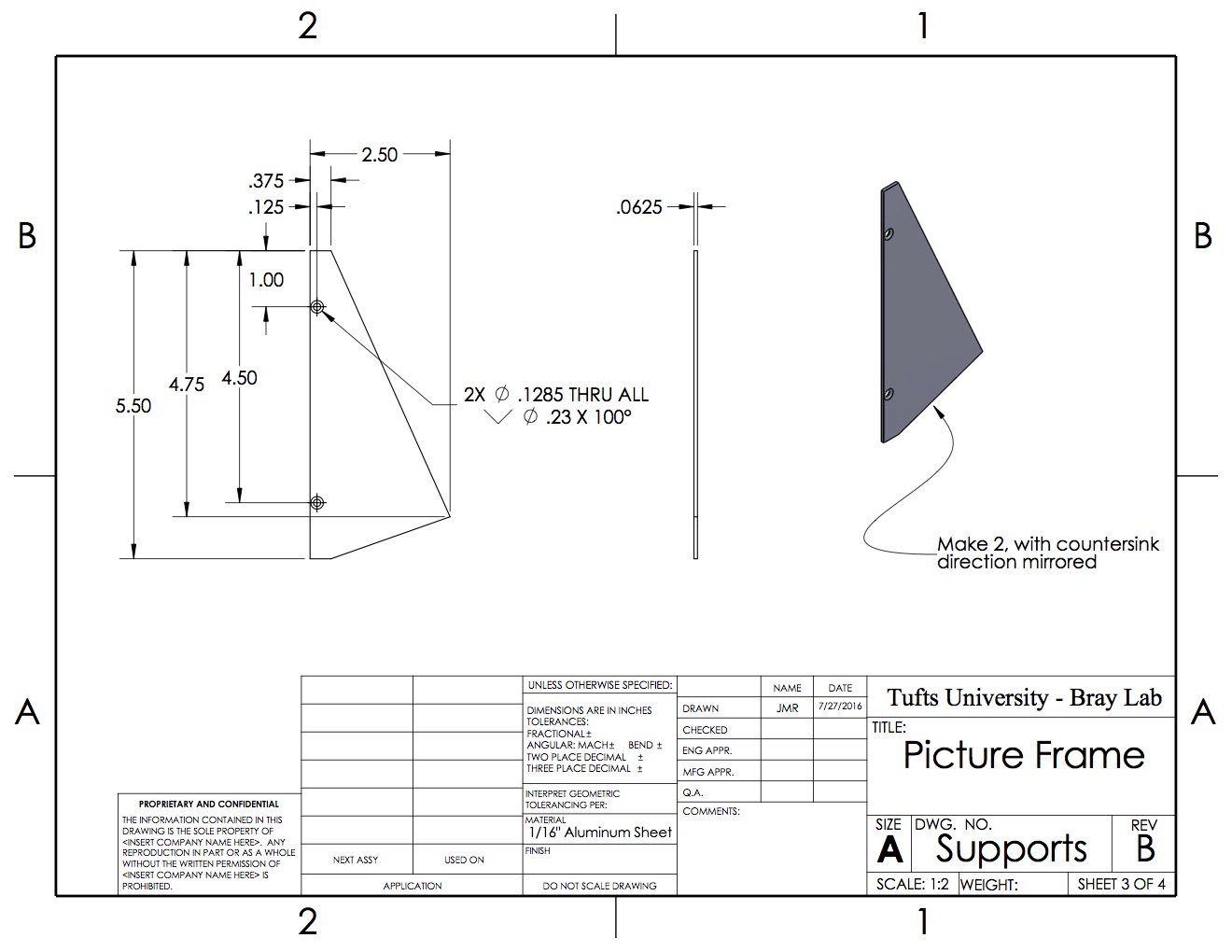
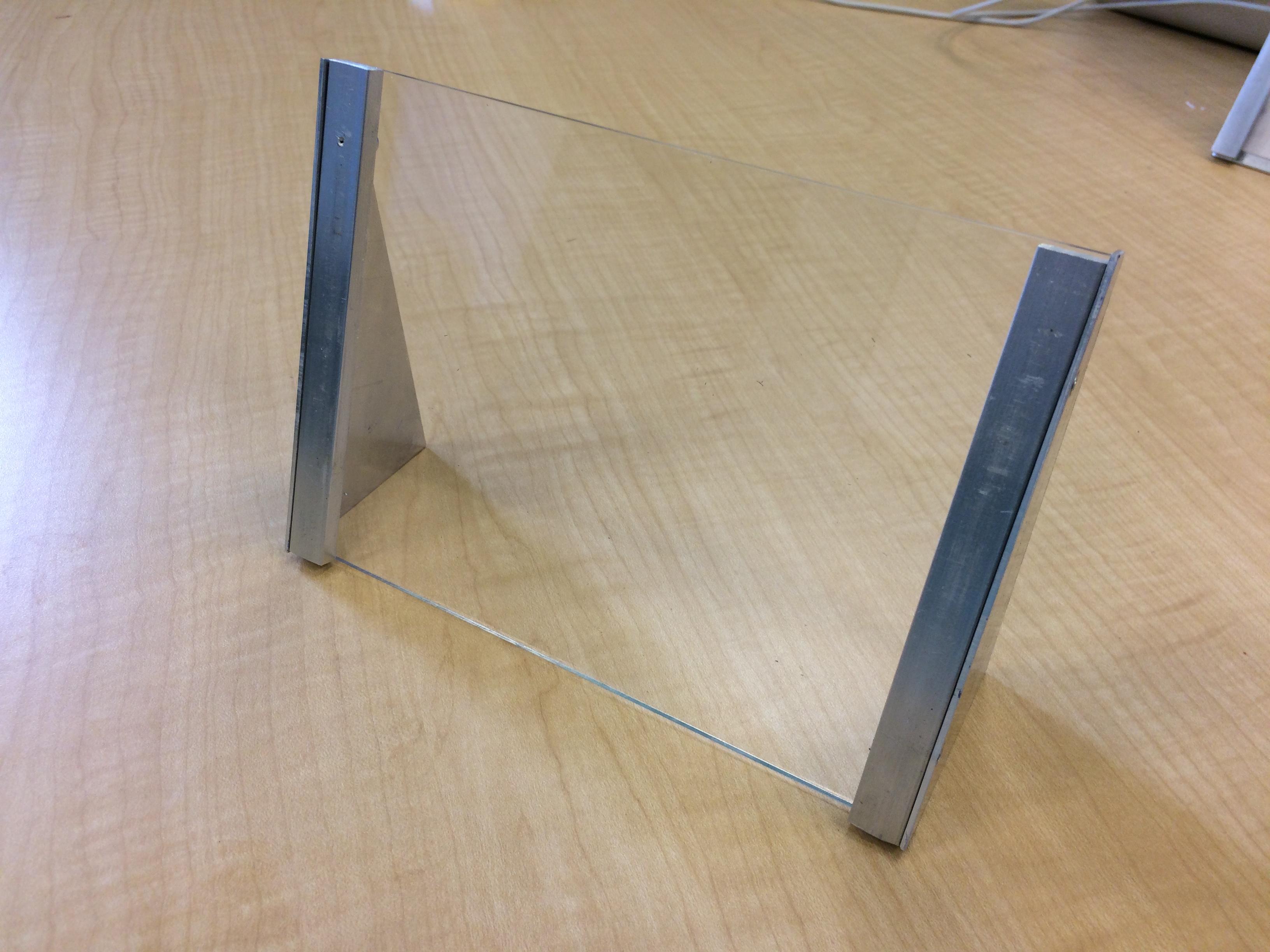
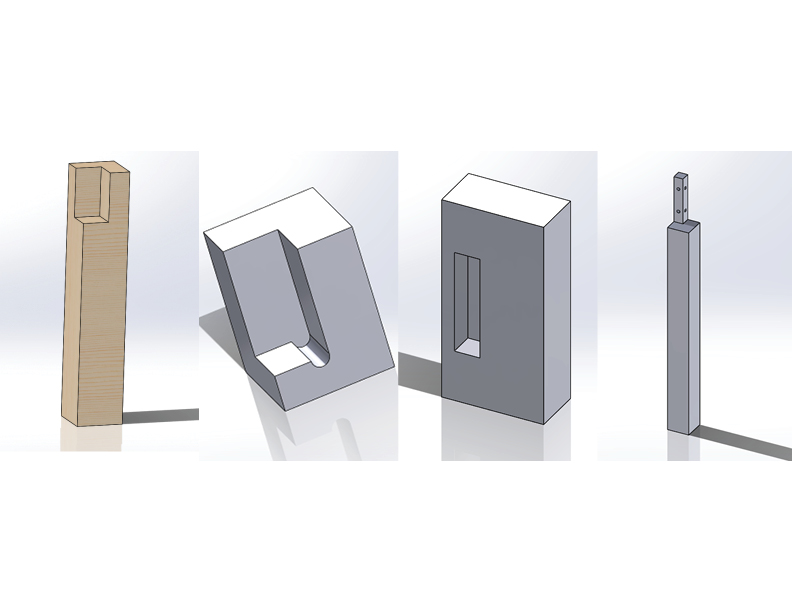
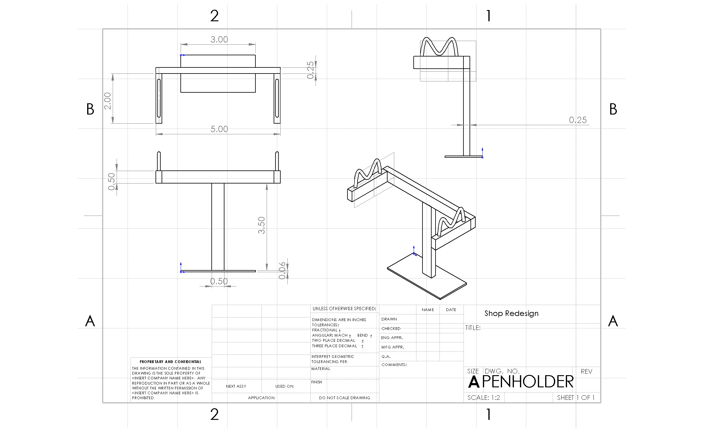
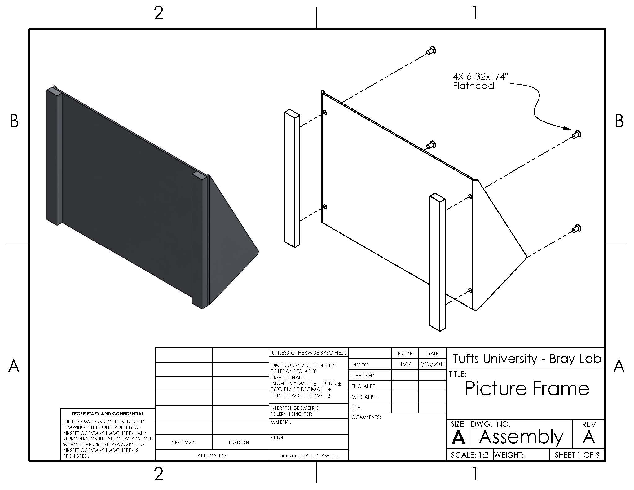
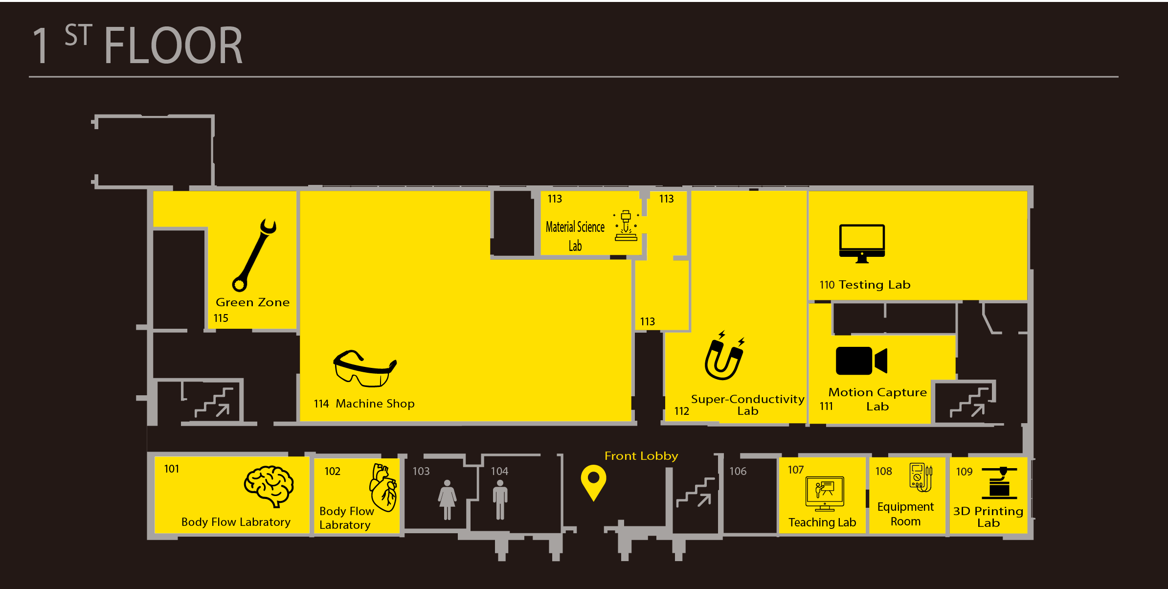
After reviewing the sketch pages, our team decided to move ahead with three concepts for a new shop training project – a pen holder, model car, and picture frame. The pen holder has a lot of room for design capabilities, and uses an appropriate amount of material for a training project, involves the use of all yellow machines plus potentially the use of the DI Wire Bender, and is practical for a college student. These qualities made the pen holder a leading candidate for fabrication as a training module. The model car, on the other hand, will probably take longer and involve more parts, but adds an element of fun and therefore more excitement. There is also a lot of room for extra design features for the car project, such as building a ramp, racing the cars, and posting the results on a leader board, or building a type of ripcord or torsional spring feature to launch the cars forward. The excitement of the car may be attractive to students, especially considering that one of the biggest problems with the wall hook was that it was boring. Lastly, the picture frame is another practical design that can be built to involve the use of all machines and is also slightly more exciting than the wall hook. However, the excitement that comes from the picture frame doesn’t come from the “fun element” like the model car, but rather from the design’s practicality. The other big problem with the wall hook was that it couldn’t be used in a dorm room. We figured that our new designs had to be either fun or practical or both in order to draw more interest in using the shop.

The next step was to ideate and create different designs for each of the concepts. Unlike for sketching, which was done on generic 8.5″ x 11″ paper, we used big sheets of paper to draw out our ideations. The goal here was to tune our concepts so they can be modeled and built well in the shop. Therefore, we put an emphasis on understanding the dimensions of the materials that the students will be working with, so we could better visualize and create ideations of our concepts that could be realistic training projects. We spent a lot of time drawing, but we also spent a lot of time discussing and building off each other’s sketches. We also wanted to brainstorm features that went outside of the realm of the yellow zone tools to add more flare and interest to the projects, while being careful to not stray too far away from the main objective of shop training. For example, we sketched out ways we could incorporate wire bending into the structure of the pen holder, or laser cut acrylic for the picture frame or bonus materials (axles and wheels) in the model car. However, as mentioned previously, it’s important to not make the project too intimidating because most of the students who are fabricating these projects probably have never spent any previous time in the shop.

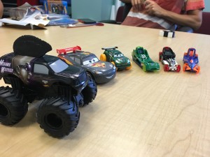
To help with our ideations, we also made a trip to Toys R Us to do some “advanced research” which involved buying and ultimately taking apart some model cars. The goal was to understand some of the more advance features of the car and to get a better sense of how we could model these features in the shop. We had a good time in the store, retrieved some heavy data from our research, and Ben even recognized some of the products he helped design. We ended up buying a few different car models, and each model had a different acceleration mechanism. Two models had a wind back and release feature meaning that when the car was rolled backwards it would propel forwards upon release, three models had a ripcord design, in which a grooved, plastic, cord would be inserted into a rotating gear that was fixed to the car’s wheel and when the cord was pulled backward, the wheel would spin forwards. The last car model had a charged acceleration method that worked by rolling the car a few times forward while keep it secure in hand, and then letting it go after a significant amount of torque was built up.

IMG_3201

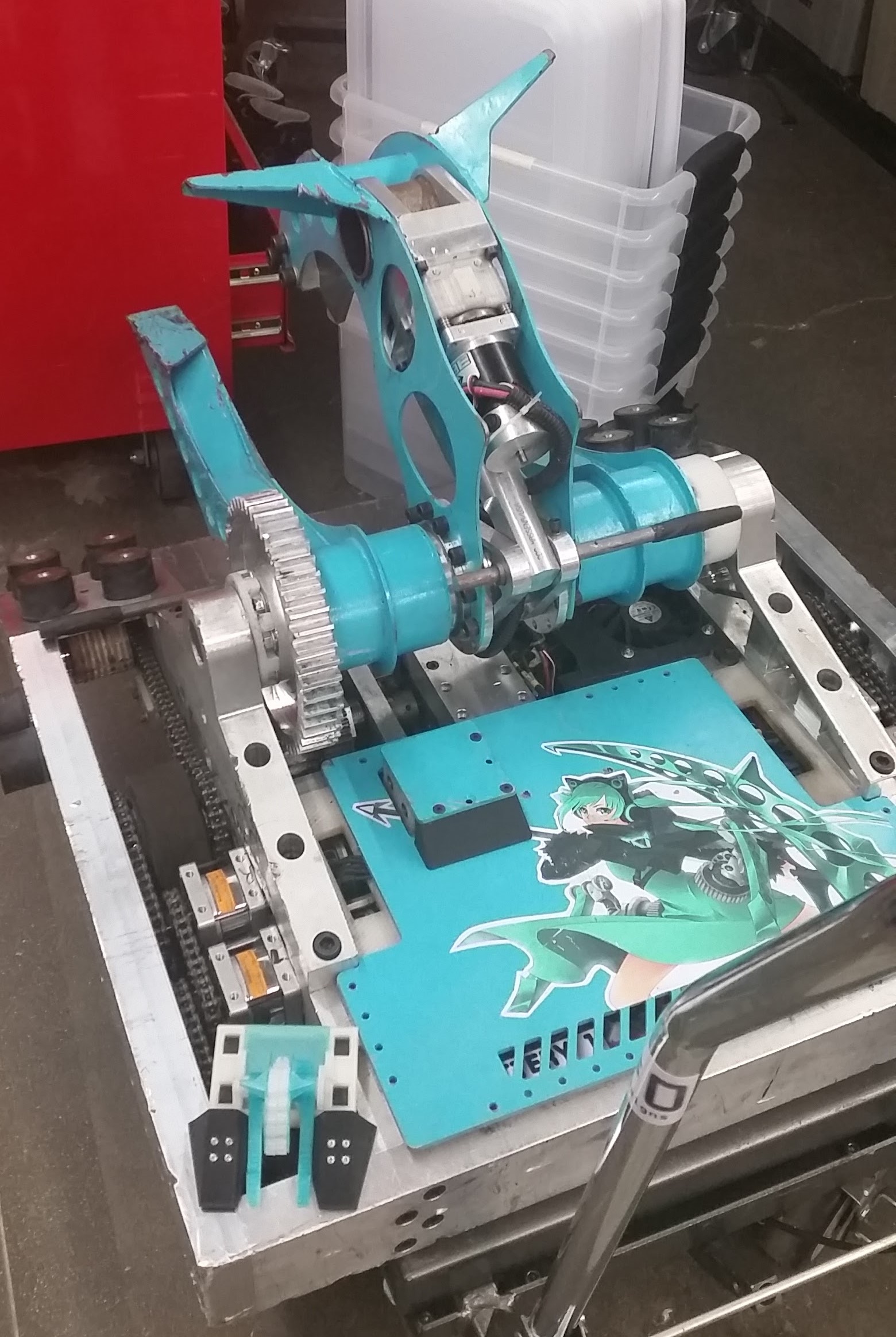
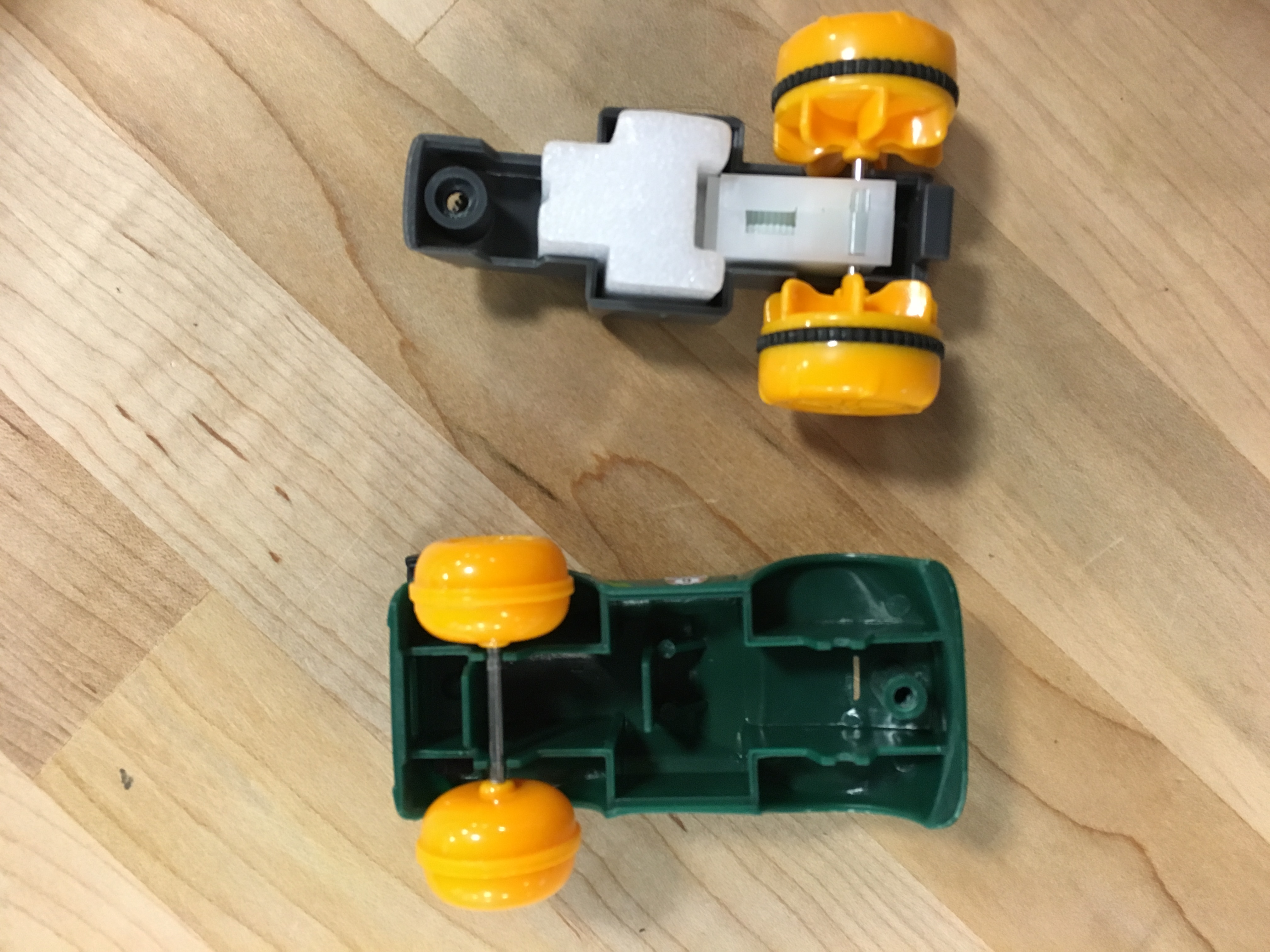
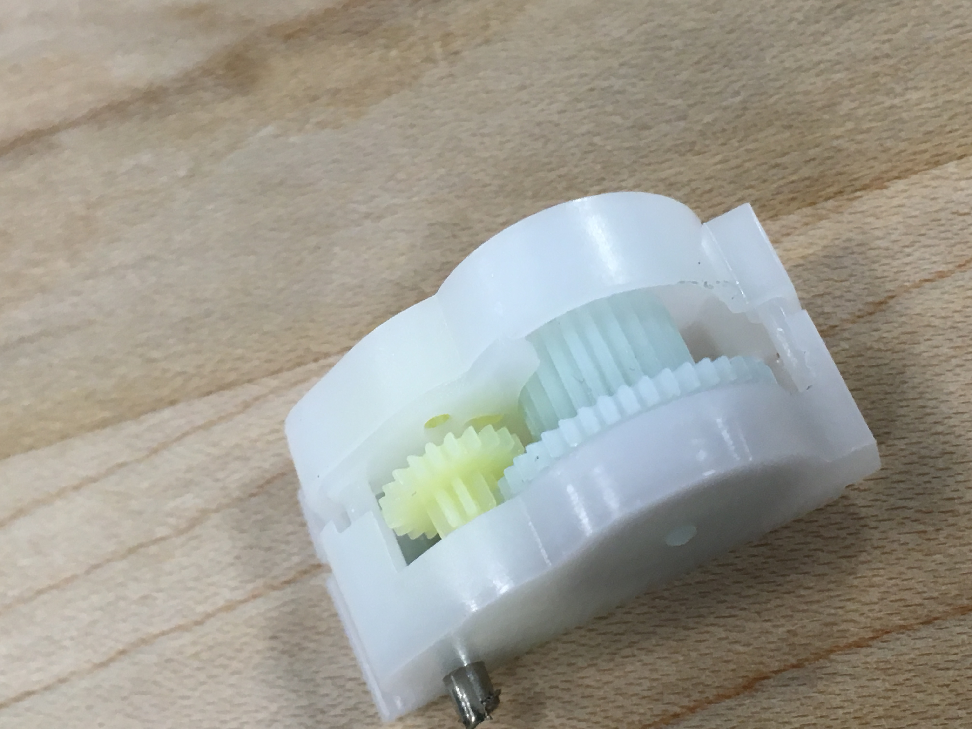
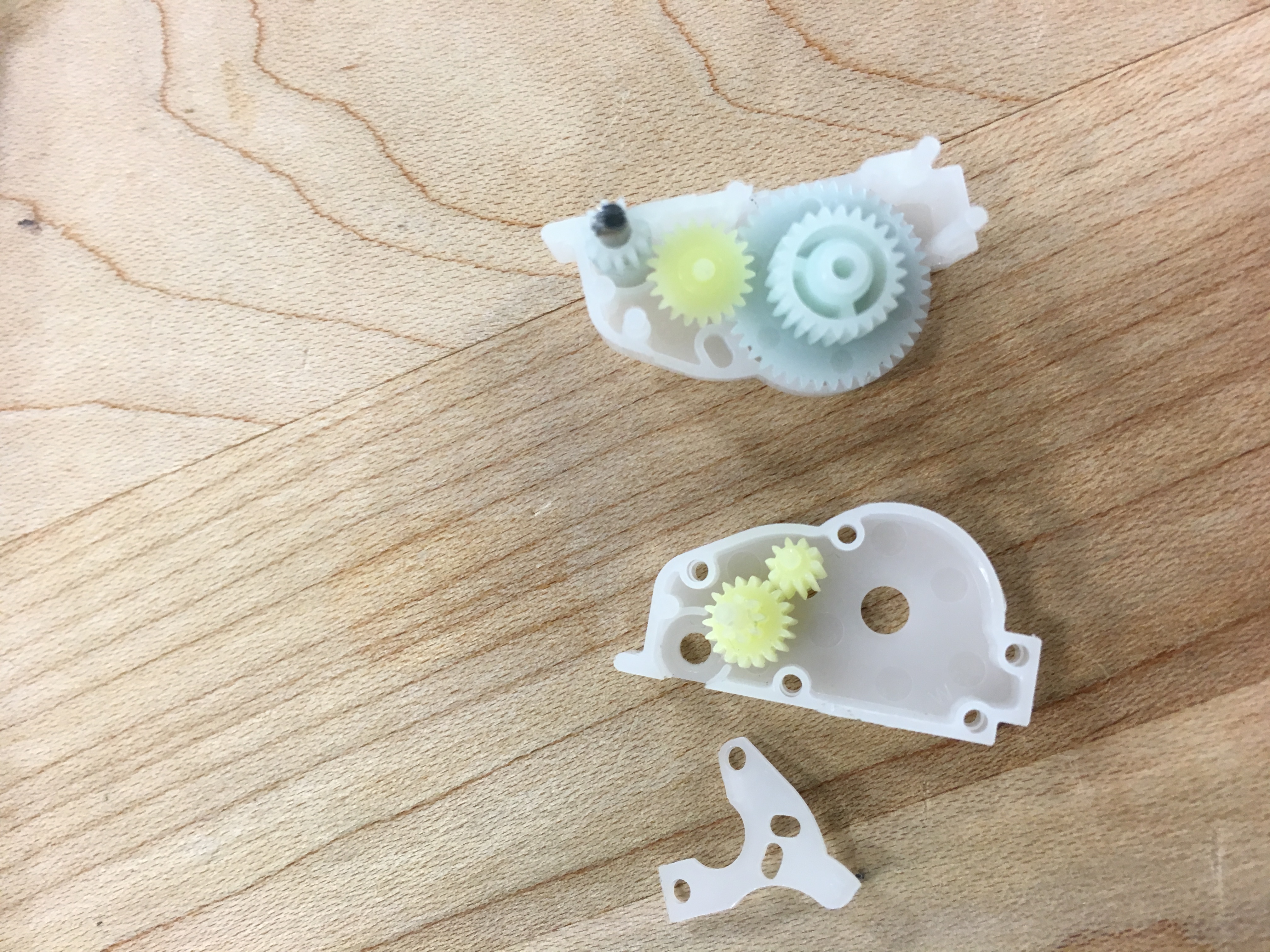
We took apart the models and examined the interior. We first looked at the two “Cars” models, which both featured the wind-back design. After breaking off the exterior shells we noticed that both models have a very similar design for their respective systems. They both featured a gearbox system that attached to a torsional spring. A gear was connected to a torsional spring on end and attached to more gears that ultimately connected with a fixed gear on the axle. When the car was released, the torsional spring would release, spinning the gear rapidly and propelling the car forward.

IMG_3203 IMG_3210 IMG_3214

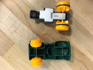
Above, we can see the gearbox system that is used to accelerate the car. The blue gear connects to the torsional spring and the green gears attach to the smaller blue gear which is fixed on the car’s rear axle. It is worth mentioning that the other “Cars” model had a nearly identical gearbox.

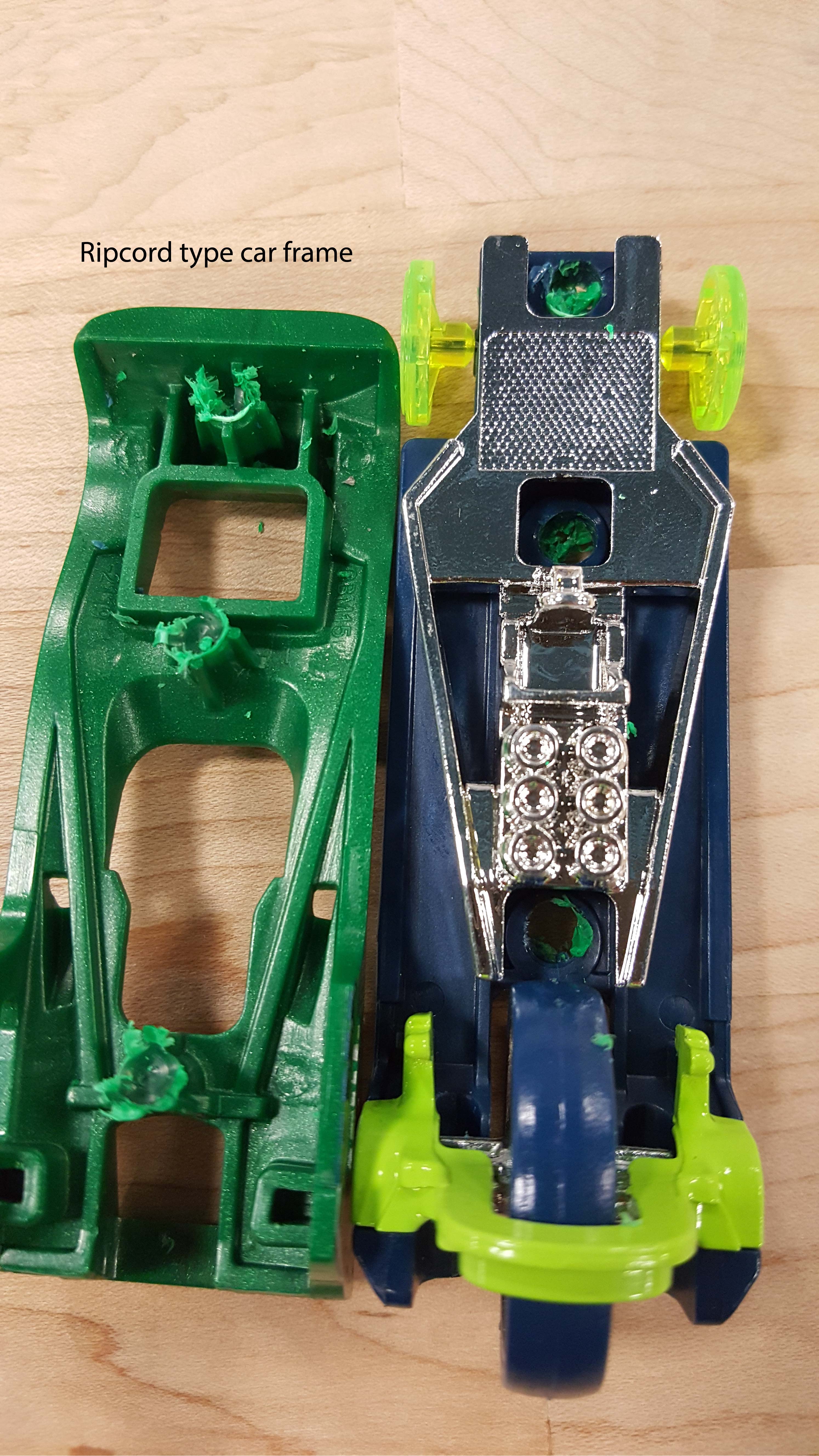
The next models we observed were the ripcord “Hot Wheelz” cars. These cars had a grooved gear attached to the rear axle. The ripcord would insert into the slot between the gear and frame, and when pulled back it would spin the back wheel, moving the car forward.

Zipcar frame20160713_154738


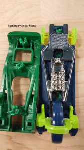
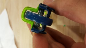
The car had a three wheel design, with a much larger wheel located in the rear of the frame. This design is something we could see ourselves emulating, because it would be relatively easy to create the gear and ripcord with the 3D printer and laser cutter and it would be a cool bonus feature to have the car accelerate without just simply pushing it forward. Creating the body of the car could be done with the use of all yellow zone tools so students could get all the appropriate training, which is the main objective of the project. This was an idea we liked, and definitely wanted to ideate further with the ripcord design in mind.

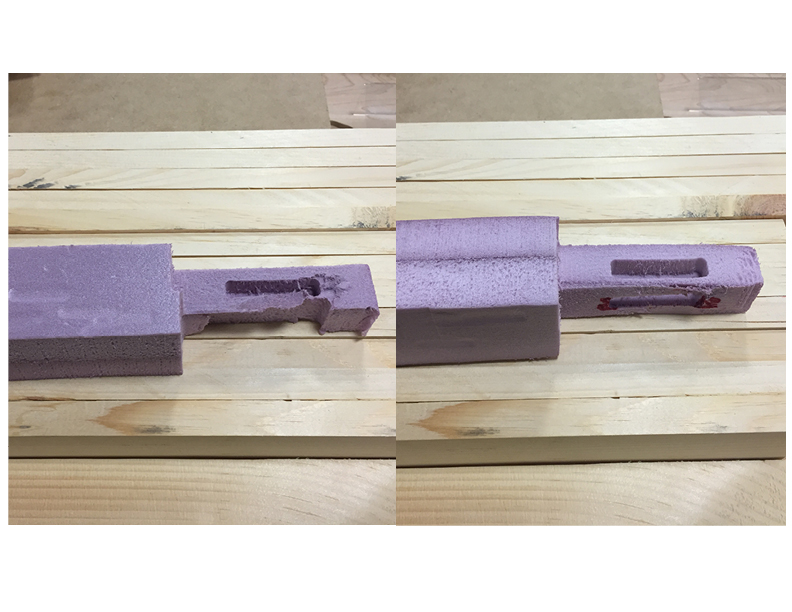
Today, there is still work to be done to create the final models of each design so they can be designed in CAD and we can begin prototyping them. This week will be spent doing just that – designing our models on Solidworks and hopefully we can begin fabricating them in the shop. Once we actually fabricate each model we will have a much better idea of the amount of materials, rigor, and time needed to build each project.


Summer Update: Coffee Table

After successfully modeling the Tufts campus in Google Sketchup and Autodesk 123D Make, I decided to test out different programs to split up the .STL file into sections that would fit on the ShopBot CNC Router.

The final .STL shown in Autodesk 123D Make

The final .STL shown in Autodesk 123D Make

The complex file was made up of too many faces to be manipulated in Solidworks, Autodesk Fusion360, or Meshmixer. So, instead of trying to take the one large file and split it up into smaller sections, I decided to go back to Google Sketchup and Autodesk 123D Make and create two smaller .STL files that would eventually be matched together.

Northern piece of the Tufts campus

Northern piece of the Tufts campus


Southern piece of the Tufts campus

Southern piece of the Tufts campus

With the two .STL files exported from Google SketchUp and imported into Autodesk 123D Make, I was able to set the material settings to be the same such that both .STL files would be sliced at the same height. Each file will have a base slice that includes most of the topography, topped by a second slice that includes only the highest points of elevation on campus. The first practice piece, shown below, helped sort out a few issues here and there with the machine setup, bit choice, and toolpaths.

First test piece of slice 1

First test piece of slice 1

After fixing those issues I was able to successfully make the two base slices of the Tufts model at a 1:3 scale.

Northern part of Tufts campus model

Northern part of Tufts campus model

Southern part of Tufts campus model

Southern part of Tufts campus model


The two halves matched together

The two halves matched together


« Older posts Newer posts »

© 2024 Bray Lab

Theme by Anders NorenUp ↑