Category: Summer Internship 2016 (Page 3 of 4)

Summer Project Update: Coffee Table

The following link will take you to the brand new CNC Router page on the Bray Lab website: https://sites.tufts.edu/bray/theshop/shopbot-cnc-router/

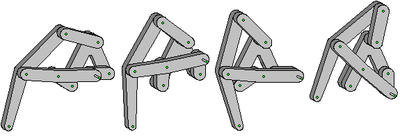
By combining the detailed information from the CNC Router’s google site with tips and tricks I have learned over the past few weeks working with the machine, I was able to organize the information and present it in a user-friendly manner.  Many photos and diagrams, like the one pictured below, were included to help new and returning users locate obscure buttons and commands.

Drawing crop

While trying to explain a chain of commands in writing can be precise and descriptive, pictures help break up the text and make the text clearer. All of the information on the Shopbot CNC Router was split up into different sub pages, to help locate information more quickly. If a user just wanted a refresher on what each kind of toolpath did, they could simply click on the ‘ShopBot File Setup’ page and skip to the ‘Toolpathing’ section. 

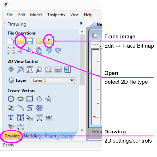
With the new section of the website completed, it was back to the coffee table. For the past couple weeks, I have been trying to find a method that would allow me to create a topographic .STL file of the Tufts University, Medford campus. My first google search brought me to a website called “Terrain 2 STL” which, as the name suggests, creates an STL file of whatever land you section off in a Google Maps window. However, the smallest size you could make the selection window included sections of Medford, Somerville, Cambridge, and Arlington, making it very difficult to decipher which large bump on the map was Tufts. With that option exhausted, I researched other methods of generating .STL files of land. One of the methods I found suggested creating a .TXT file with the latitude, longitude, and elevation coordinates of various point round Tufts and importing them into Solidworks to make a “point cloud.” While the Youtube tutorial of this process created a clear, smooth solid of the terrain, I was left with hundreds of triangles that produced a stalagmite-looking object. I scoured Solidworks forums and maker space blogs searching for a way to create this file, and clearly I was not the only person eager to 3D print or CNC their own topography. Thankfully, this morning a new method involving Google Maps and SketchUp was suggested to me. With some quick internet searching, I found this tutorial, followed along with only a few hiccups, and was able to generate an accurate, detailed .STL file of Tufts.

The final .STL shown in Autodesk 123D Make

The final .STL shown in Autodesk 123D Make

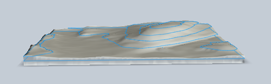
Since the model will be about 24″x36″x4″, it will need to be cut in sections on the ShopBot CNC Router. Autodesk’s 123D Make is a versatile CAD software that will slice a 3D model using various slicing techniques.

In the upcoming week, I hope to start practicing making this piece on the XPS foam, finding the optimum slicing technique, and researching more joinery methods with which to assemble the table!

Revitalizing Malden High School’s Workbenches

One of the largest engineering spaces currently missing from the Tufts campus is a student-accessible wood shop. But over at Malden High School, professors and Tufts students are working to create a fully-equipped wood shop/makerspace in Nedlam’s Workshop, a mere ten-minute drive from Tufts. Several of us spent the last few days there learning about the tools and working to improve the space, cleaning it up and creating new and improved work spaces around the shop. My team’s particular focus was the shop’s four solid maple workbenches, each of them a beautiful butcher’s block work surface covered in years of varnish, paint, and grime. Our task was to clean up and stabilize the decrepit worksurfaces and solidly remount the woodworker’s vices loosely hanging off each bench.

A quick experiment with a planer and then handheld sanders revealed that the built-up coatings were more than a match for our tools. The layers of varnish quickly clogged sandpaper, and hidden nails blocked progress with the planer for fear of chipping the blade. But a much easier solution quickly presented itself: flip the table tops over. Four easily-removed bolts secured each top to the base, and with them out of the waywe found bottom surfaces in near-mint condition. Some wood filler, scrapers, and a little bit of sanding took care of years of holes and gum within minutes.

Our other challenge, then, was to mount the vises. The vises had originally been mounted with lag screws, which, while solid, will (and had) eventually strip out a hole. So instead of screws, we used carriage bolts to secure the vises through the table. The bolt heads were counterbored – sunk into the tabletop so as to sit flush – and secured on the bottom with nuts and washers; additionally, the vise faces were screwed into the table face. This secure mounting mechanism will allow the hardware to be continually re-tightened whenever it loosens, something not possible with lag screws. The finished workebenches were much more solid, smooth, and easily usable – and stylish to boot.

Biomimetic Mover – Days 1 and 2

The past two days have been spent working on the Biomimetic Mover project. The project is aimed at creating a device that is able to simulate any sort of planar movement along a flat surface without the use of wheels. Jonathan Rooney and I have spent our time trying to work on a mechanism that uses the Klann linkage technique, which is a method that simulates a spider-like gait. A diagram from Wikipedia for each position in the Klann linkage cycle is show below:

F1-positions

The diagram shows the linkage in the fully extended, mid-stride, retracted, and lifted position. In the diagram, the right most link with the extended pin is fixed to a gear. The gear rotates the link and drives the motion of the system.

After it was determined that the Klann linkage was going to be modeled after, we brainstormed ideas about certain design features. After a lot of thinking, we came to conclusions on the first prototype. We then used the software package OnShape to design the links and frame to match our sketches and plans. A few of the links are shown below:

Screen Shot 2016-06-15 at 4.36.43 PM

Link drawings on OnShape

We then uploaded the OnShapes .dxf files into the laser cutter and cut our pieces out of 1/8″ acrylic. It is worth noting that the design of the links and frame are something that have remained consistent throughout our entire design process.

Once we had our components, we thought more about how the legs are going to work in tandem to create the desired walking motion and made some changes along the way. We stand today deeply engaged in the building stages, with a goal to create an eight-legged mechanism with two vertical, hexagonal frames, and a gear assembly. There is a pair of legs on each end of the frame, with each leg attached to a gear.  The gears are connected to each other with a threaded bolt and the two legs are connected to each gear with each connection 180 degrees apart. So when the gear is driven, one leg will left up and the other will touch down. This happens in tandem with all of the four leg pairs, so hopefully if designed properly this will create the walking motion.

Walker Frame

These pictures show one of the linkage systems connected to the mounted gear. Also additional leg structures, bolts, and spacers are shown. All of the link pieces, the gears, and the spacers were laser cut.

We have encountered some problems along the way with spacing. We have had to figure out ways to space the linkages so they can flow well as the gear spins. Countersinking the acrylic frame and gears, laser cutting custom spacers, and using various bolts of different lengths have all been methods we have used to ensure the system can work. We also have had issues with hole sizes because we have had to change bolt sizes often, so we’ve have to recut many pieces.

The video below demonstrates how driving the gear generates the motion of one of the legs. Instead of my hand, there will be a central gear which connects to another gear on the other end, making a three gear system. This will occur on the side of this frame as well, and then it will be symmetrically reproduced on a second frame, totaling 12 gears. The two plates are connected and hopefully we will have a functioning biomimetic mover.


« Older posts Newer posts »

© 2025 Bray Lab

Theme by Anders NorenUp ↑