Compression Test Machine Setup
For a Compression test, the following fixtures and components are required:
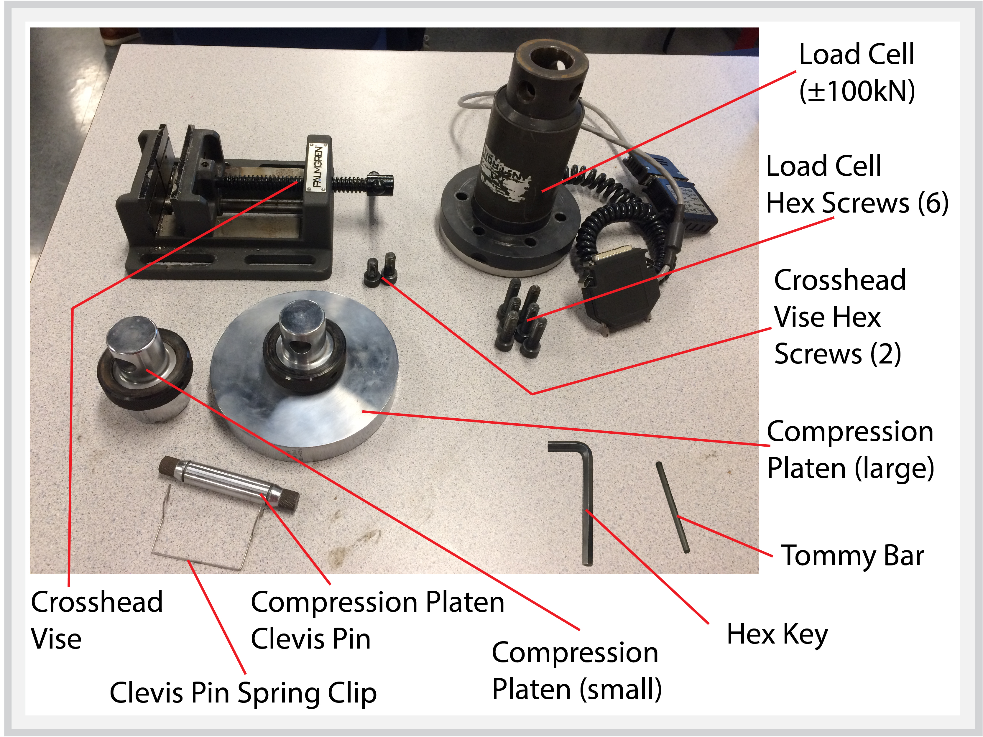
○ Load Cell (±100kN)
○ Load Cell Hex Screws (6)
○ Crosshead Vise
○ Crosshead Vise Hex Screws (2)
○ Compression Platen (large)
○ Compression Platen (small)
○ Compression Platen Clevis Pin
○ Clevis Pin Spring Clip
○ Tommy Bar
○ Hex Key
NOTE: There are various compression tests that can be performed on various material specimen geometries. The following machine setup example is for a compression-deflection test of a 90-degree angle beam.
1. Install Load Cell
- Make sure there is no Load Cell currently installed in the Load Frame.
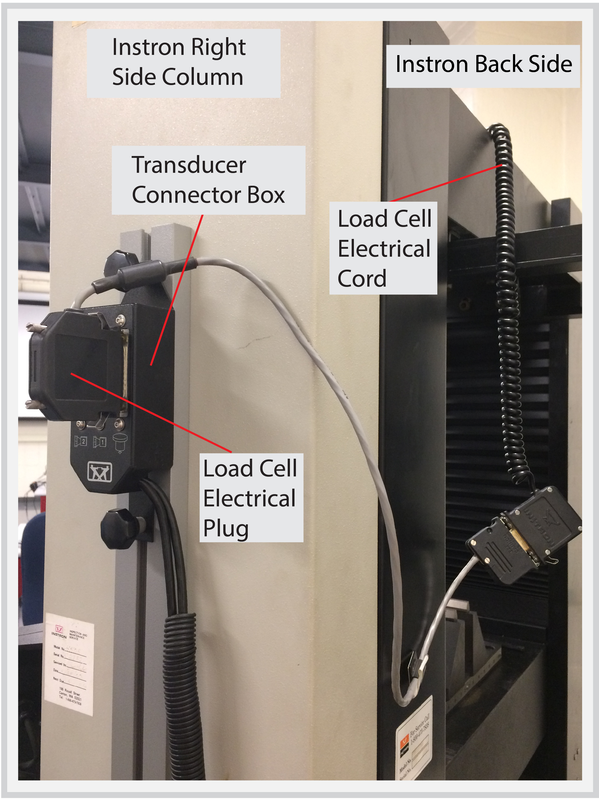
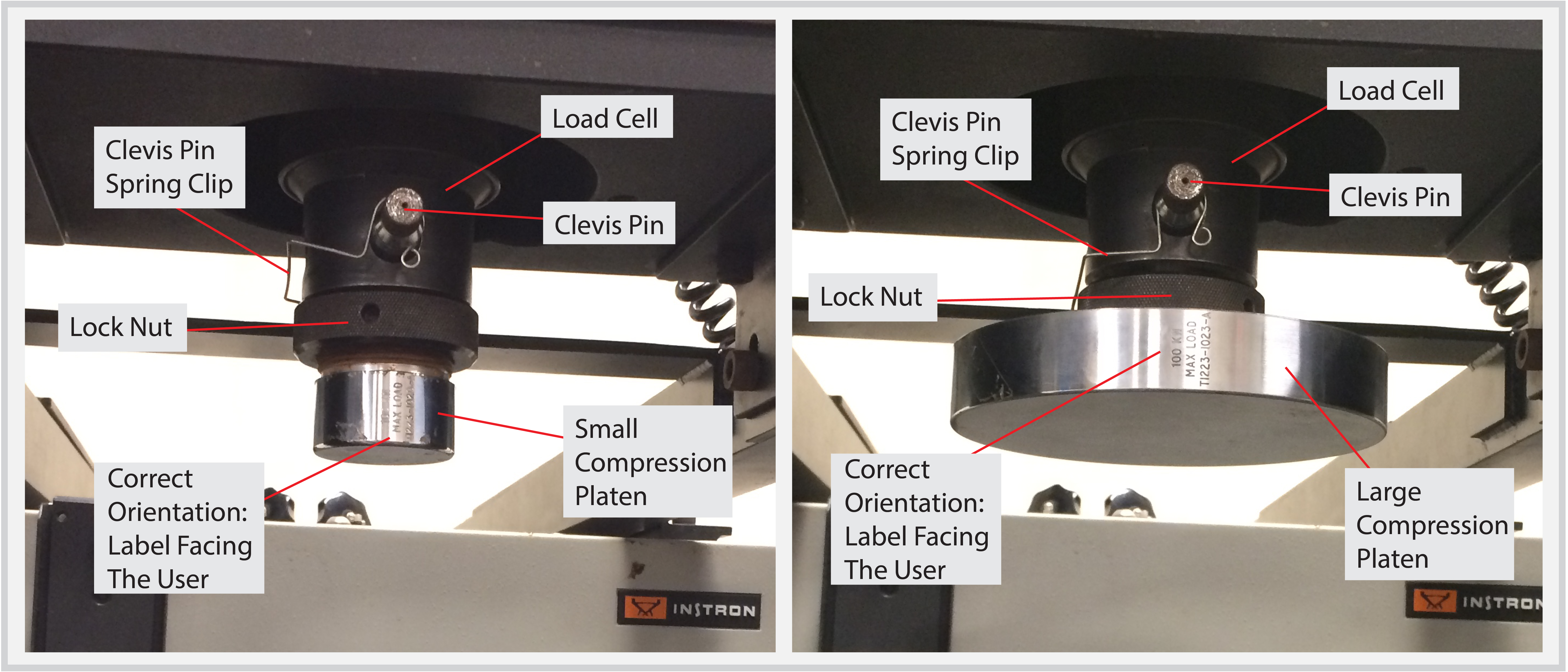
- Insert the ±100kN Load Cell into the top of the Load Frame making sure that it is in the correct orientation (i.e., the wording on the label is facing the operator).
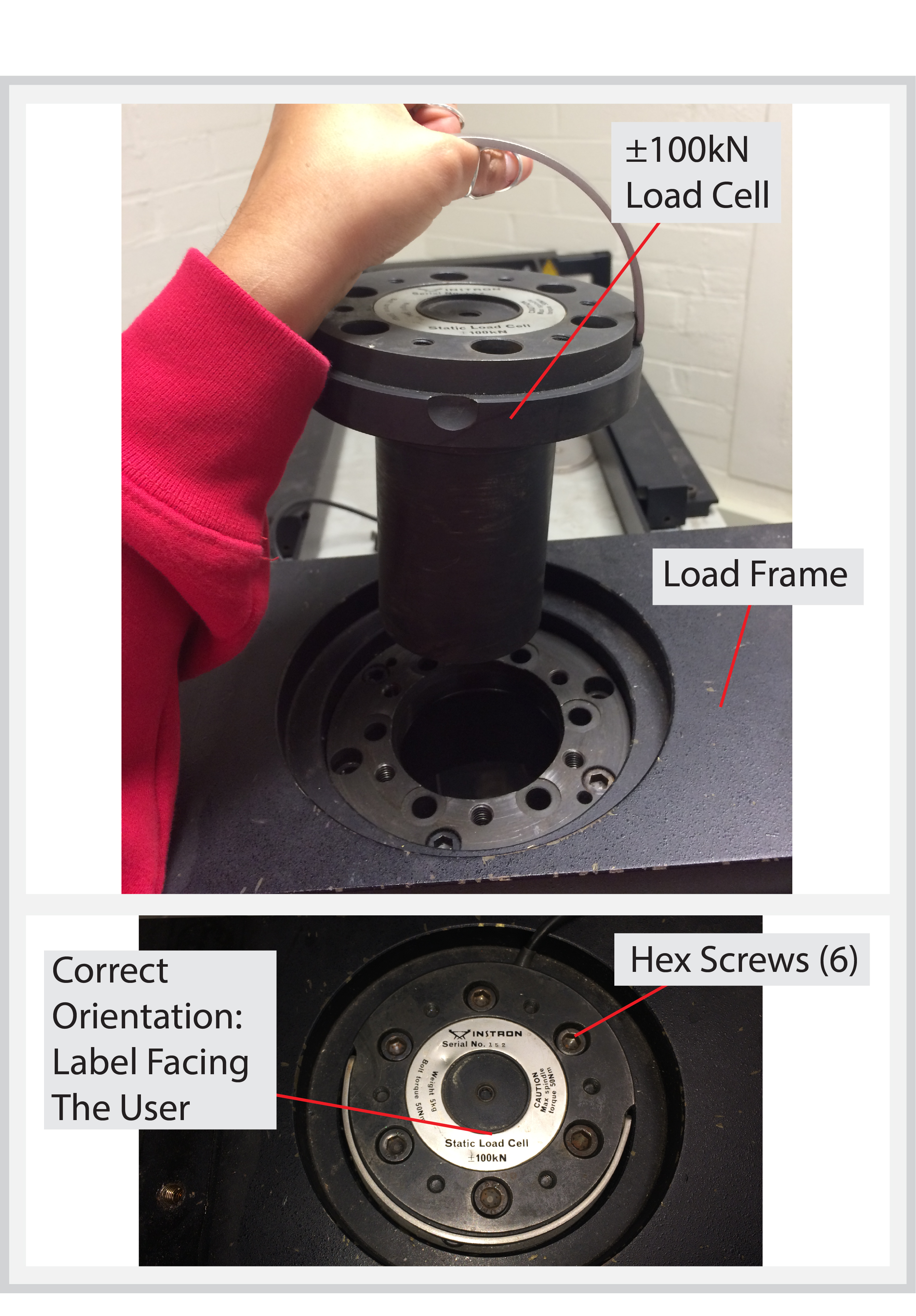
- Attach the Load Cell to the Load Frame using 4-6 Hex Screws.
- Plug the Load Cell into the Transducer Connector Box.
- On the Desktop Computer, start up the Bluehill application software. This will enable the jogging operation of the Crosshead.
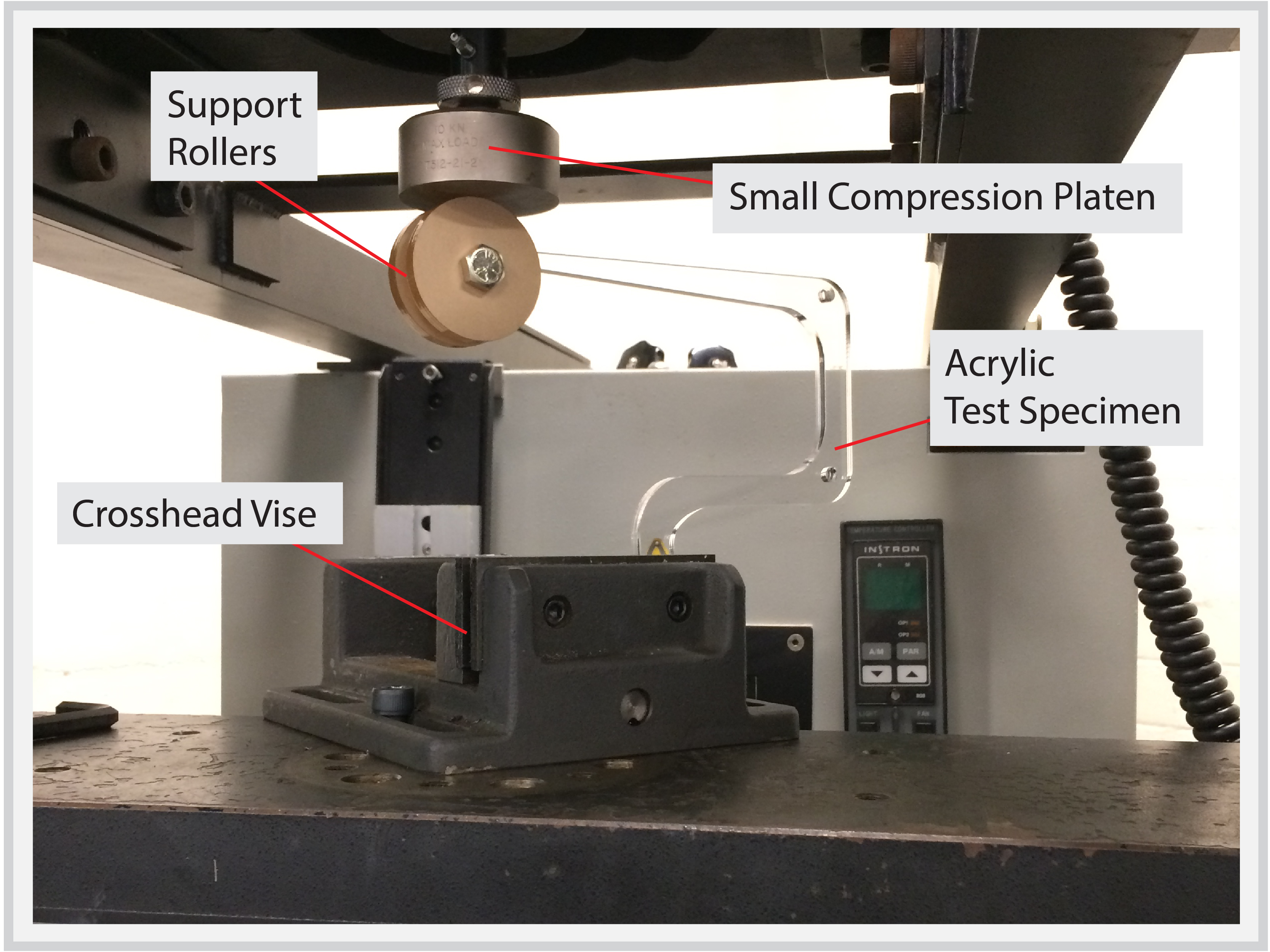
2. Install Compression Platen
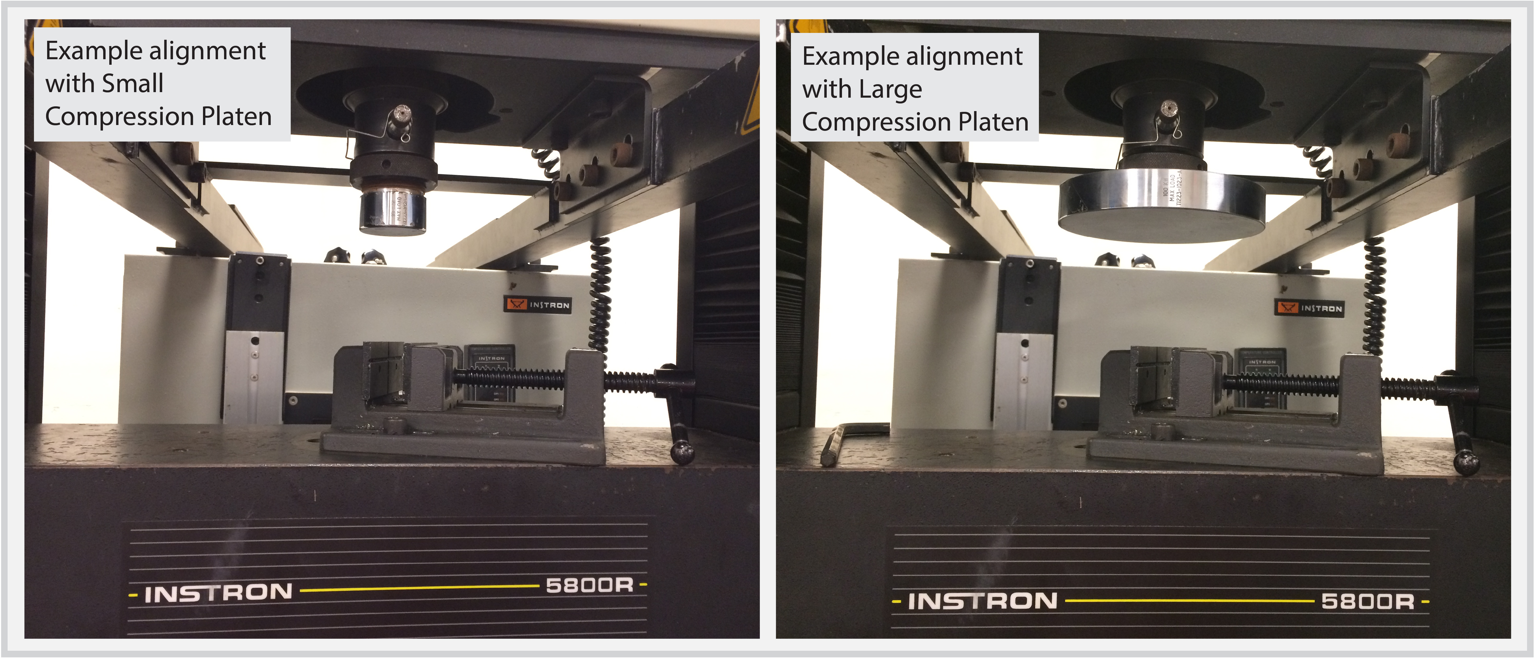
- Two sizes of Compression Platen are available: large and small. Platen size should be determined by what test is being run, and the size and shape of the material specimen.
- Insert the Compression Platen into the Load Cell and secure it with a Clevis Pin.
- Use the Tommy Bar to hand-tighten the Lock Nut against the Load Cell.
- Attach a Spring Clip to the Clevis Pin.
3. Install Crosshead Vise
- Make sure all previous fixtures have been removed from the Instron.
- Place the Crosshead Vise onto the Crosshead. The Crosshead Platen should be attached to the Crosshead using at least 2 Hex Screws.
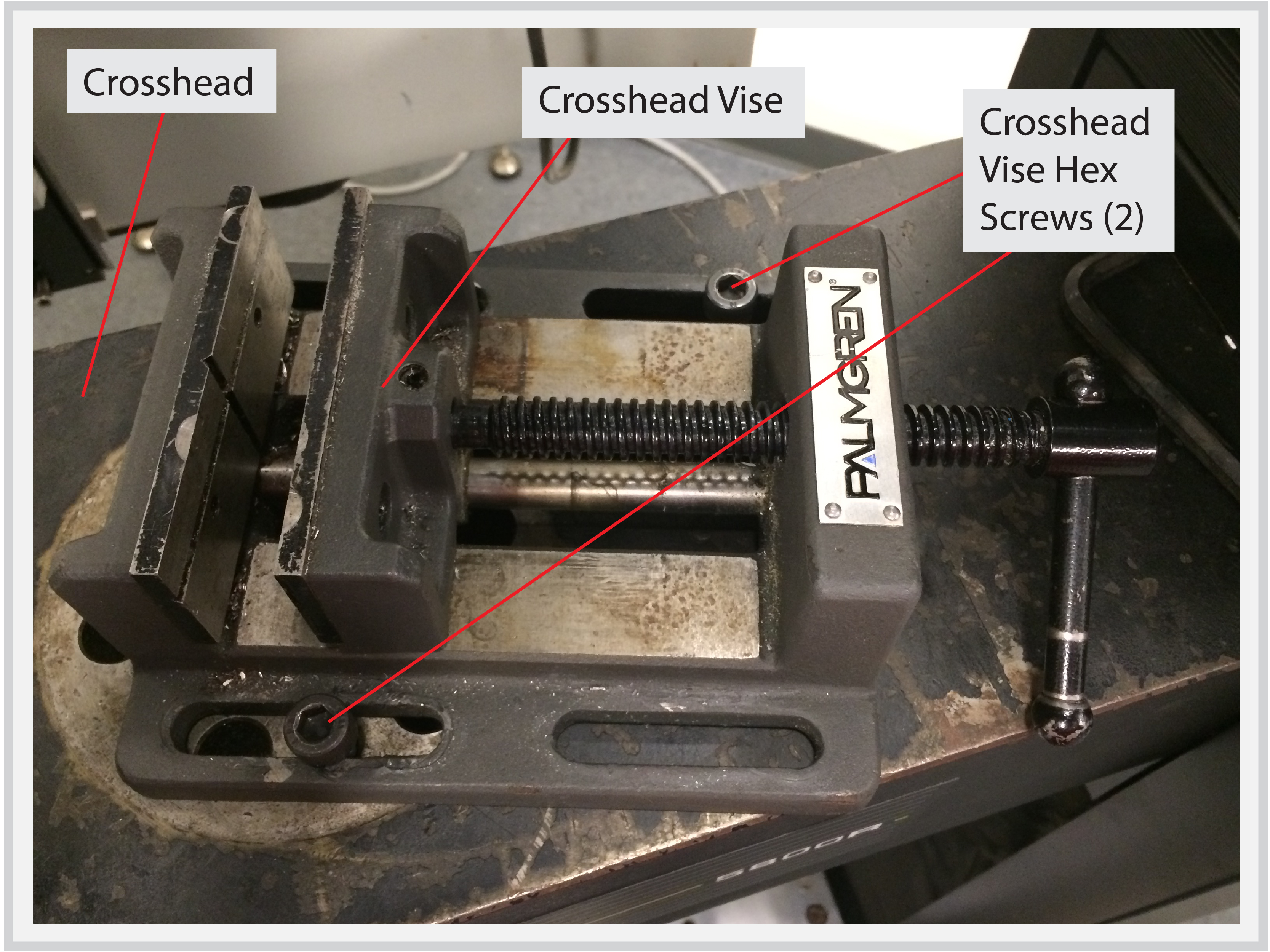
- There are several ways the Vise can be oriented and aligned with available screw holes. This orientation should be determined by how the Compression Platen is expected to interface with the material specimen.
4. Install Material Specimen
- The following material specimen installation is for a compression-deflection test of a 90-degree angle beam. Acrylic support rollers were fabricated and attached to the specimen to reduce testing friction and to direct the compressive load.
- Clamp the material specimen vertically in the Crosshead Vise, and align the support rollers to be centered beneath the Compression Platen.
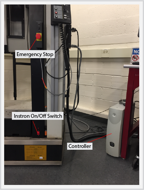
5. Turn on Instron
- Flip the Instron On/Off switch to on, it is located on the bottom right of the front face of the Instron.
- Check that the emergency stop (e-stop) is disengaged. If the e- stop turns easily to the right it is disengaged. If it is engaged, turn it to the right until it pops to the disengaged position.
- Turn on the controller using the switch towards the bottom of the back of the unit.
- You are now ready to perform a Compression Test. Please refer to the next section on Software Setup for programming and running the test using the Bluehill software.