Nexus Motion Capture Lab Instructions
System Setup
Initial Setup
- Plug power cord into PoE+ switch
- Cameras should power on (camera number shows on display screen)


- Cameras should power on (camera number shows on display screen)
- Open Vicon Nexus 2.10.1
- Make sure viewing window is set to “3D perspective”
- (screenshot of window cropped to “3D perspective” option in dropdown menu)
- In “resources” window, make sure system is online. If not, click “Go Online” button

Calibration
- Make sure system is live
- In “resources” window, highlight all 12 cameras under “Vicon cameras”
- In viewing window, change view to “camera view”
- In “tools” window, click “system preparation tools” icon
- In the “wand” dropdown menu, select “active wand”
- In the “L-frame” dropdown menu, select “active wand”
- Under “calibrate cameras” select “advance settings”
- In the “calibration type” dropdown menu, select “full calibration”
- In the “cameras to calibrate” dropdown menu, select “all cameras”
- Make sure refinement frames is set to [???] and DV calibration frames is set to [???]
- Select “start”
- Turn on active wand
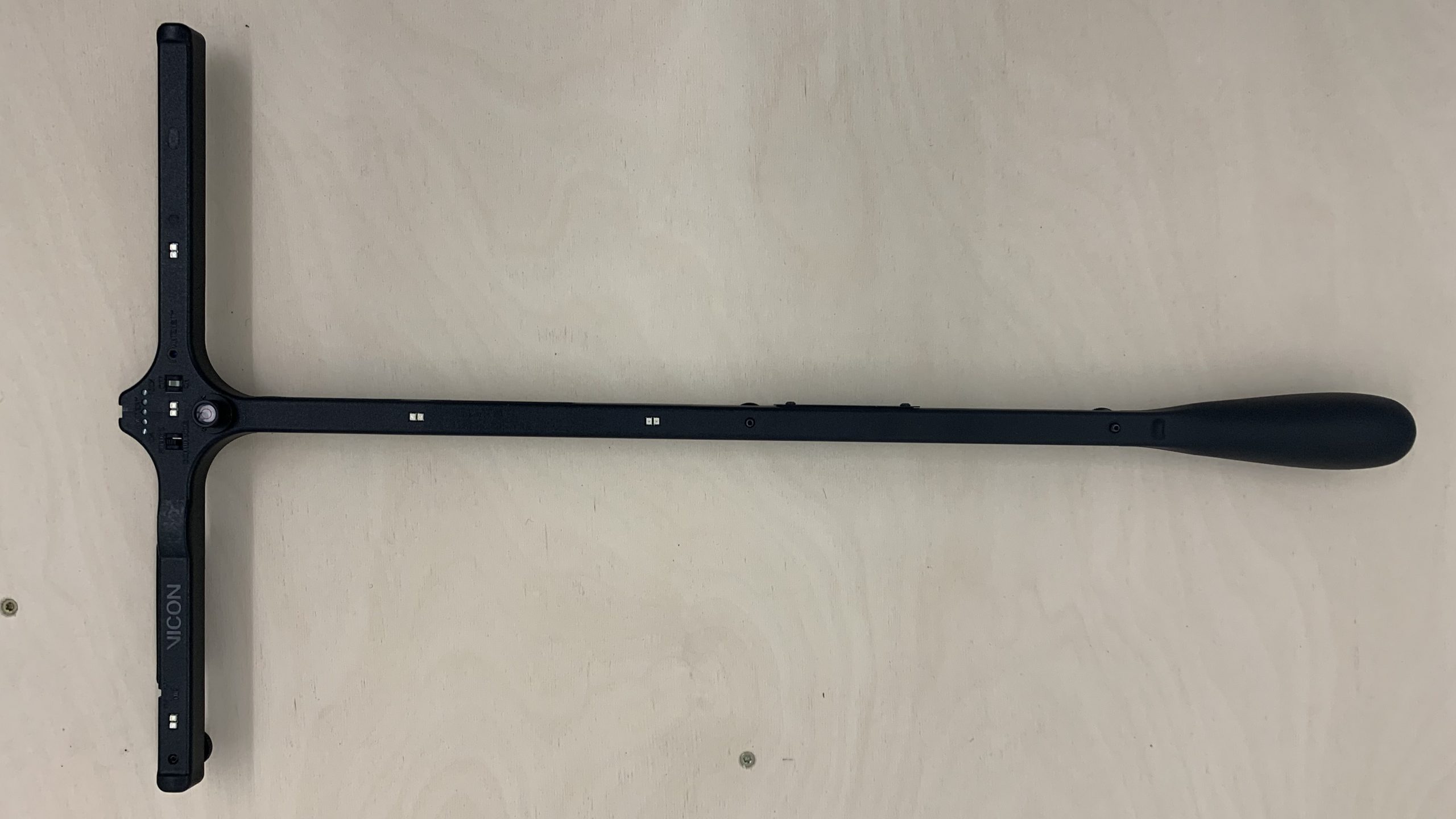
- Wave wand around in capture volume, with LEDs facing cameras
- Objective is to cover as much of each camera’s FOV as possible
- Each camera display will show a pie chart that becomes increasingly full as more area is covered by the LEDs. The camera is fully calibrated when the pie chart is completely full. Wave the wand until all cameras are calibrated
Vicon Nexus Skeleton
Creating New Skeleton
- Place markers on subject using marker fixing tape
- Minimum 2 per segment (e.g. thigh, torso)


- Minimum 2 per segment (e.g. thigh, torso)
- Capture subject markers
- Record 3 seconds with the subject static (i.e. not moving)
- Build Skeleton
- Reconstruct the recorded static data to see points
- Create Segments (repeat until all segments are created)
- Note: (not confirmed) when selecting markers of each segment start proximally and go distally (e.g. start with torso -> thigh -> shank -> foot, where the first marker is on or near the previous segment)
- Create Links (repeat until all links are created)
- Relabel markers so that each one describes the location on the subject (e.g. Right_Foot_BigToe, Left_Thigh_MidThigh)
- Reconstruct and Label to check your work
- Range of Motion Trial (not required)
- Record the subject going through the full range of motion of each joint
- Reconstruct and Label to look for where the tracking failed
- Functional Calibration (finding joint automatically)
- If failures in labeling occur, this may need to be done
- Complete: start taking data
Using Existing Skeleton
- Place markers on subject
- Number of markers and their positions is determined by the skeleton being used
- Capture subject markers
- Record 3 seconds with the subject static (i.e. not moving)
- Manually Label Markers
- Reconstruct the recorded static data to see points
- Load the existing labeling skeleton template.
- Manually select each marker of the labeling skeleton and its corresponding marker in the static trial (repeat until all markers are attached to a label)
- Reconstruct and Label to check your work
- Range of Motion Trial (see section 4 above)
- Complete: start taking data