ShopBot Software Setup
1. Setup file in VCarve
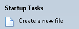
- Open VCarve

- Select ‘Create a new file’
- Measure length, width, and height of your raw material. Enter these dimensions under ‘Job Size.’ It’s very important that the XY datum and Z zero is set as shown in the picture below. If not, serious damage to the machine and work piece could occur. Required setup:
- Zero Z to top of the material
- Set XY datum to bottom left corner
- Make sure that the offset is set to X: 0.0 and Y: 0.0
- Check units!

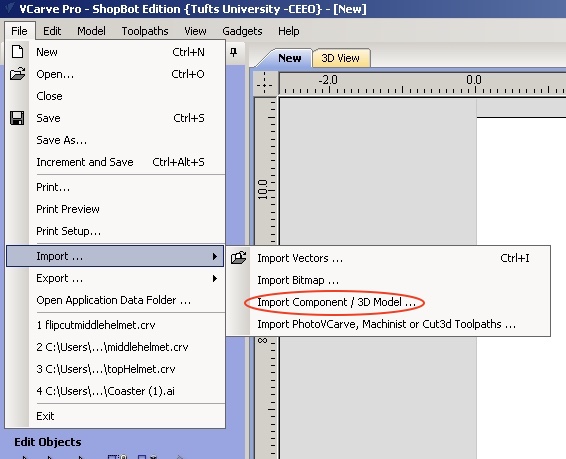
- Import file into VCarve: click on File -> Import
- 2D file (.dxf, .ai, .pdf, .dwg)
- Recommended software: AdobeIllustrator, AutoCAD
- 2D file (.dxf, .ai, .pdf, .dwg)

- 3D file (.stl, .obj)
- Recommended software: SolidWorks
NOTE: After importing an .STL file, check the object’s dimensions in VCarve because objects tend to be scaled larger than the actual size.
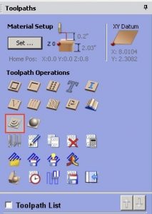
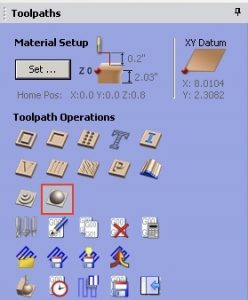
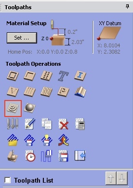
2. Toolpathing
In order to cut a part, a toolpathing file must be created. The toolpathing file is the path that the bit follows to produce the desired work piece.
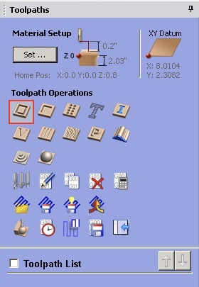
- In the top menu bar, select “Toolpaths” -> “Show Toolpaths Tab”
- Select the kind of toolpath you would like to make first, then click the desired vector in your workspace
Types of Bits:
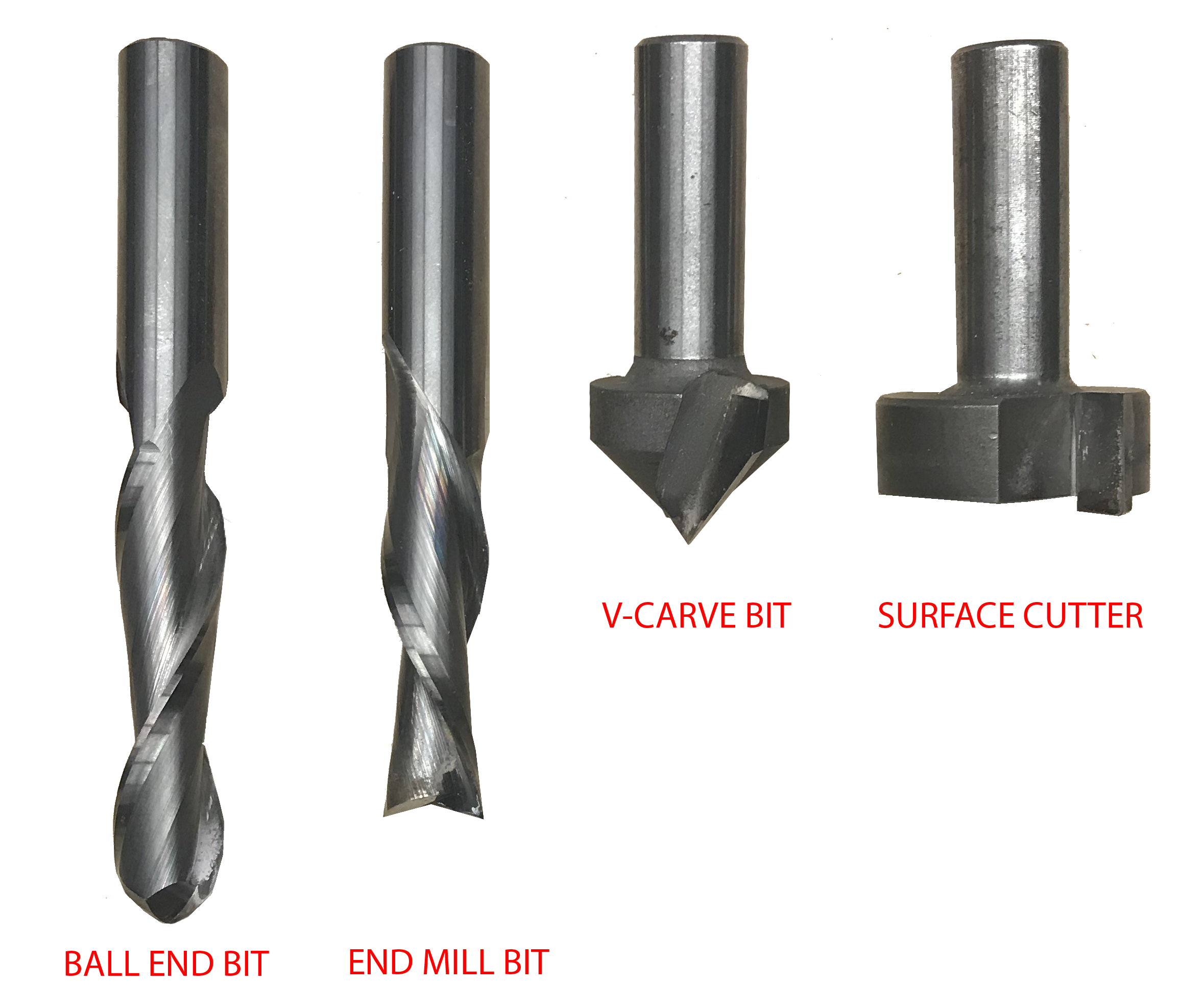
- End Mill: good for straight cuts and for hogging out a lot of material (ie. for a roughing toolpath)
- Ball-Nose: good for contours, details, and finishing paths
- Profile (such as a V-Carve): good for lettering and sign-making
- The larger the bit the better (quicker mill and less likely to break).
- Vcarve automatically sets a max cut depth so you must change it to actual material depth
Most common types of toolpaths:
- 2D Profile cut: Cuts along a specified boundary, great for cutting a smaller piece out of a larger piece


- 2D Pocket cut: Cuts out all material within a specified boundary, good for shelling out material


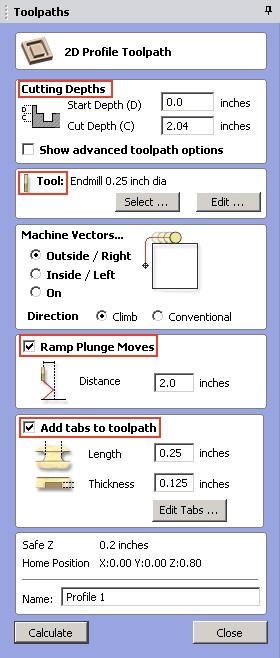
- Setting Up 2D Toolpaths (please follow the required steps carefully)
- Make sure that the Start Depth and Cut Depth does not exceed the thickness of your material. Not doing so could result in damage of your work piece and the machine.
- Select the correct tool according to the material type and dimension of your piece. **Do not change the tool presets
- Make sure you add a Ramp Plunge Move of at least 2.0 inches.
- Add Tabs to your toolpath to prevent your piece from spinning on itself. Add at least three tabs to make sure piece stays in place during the cut.
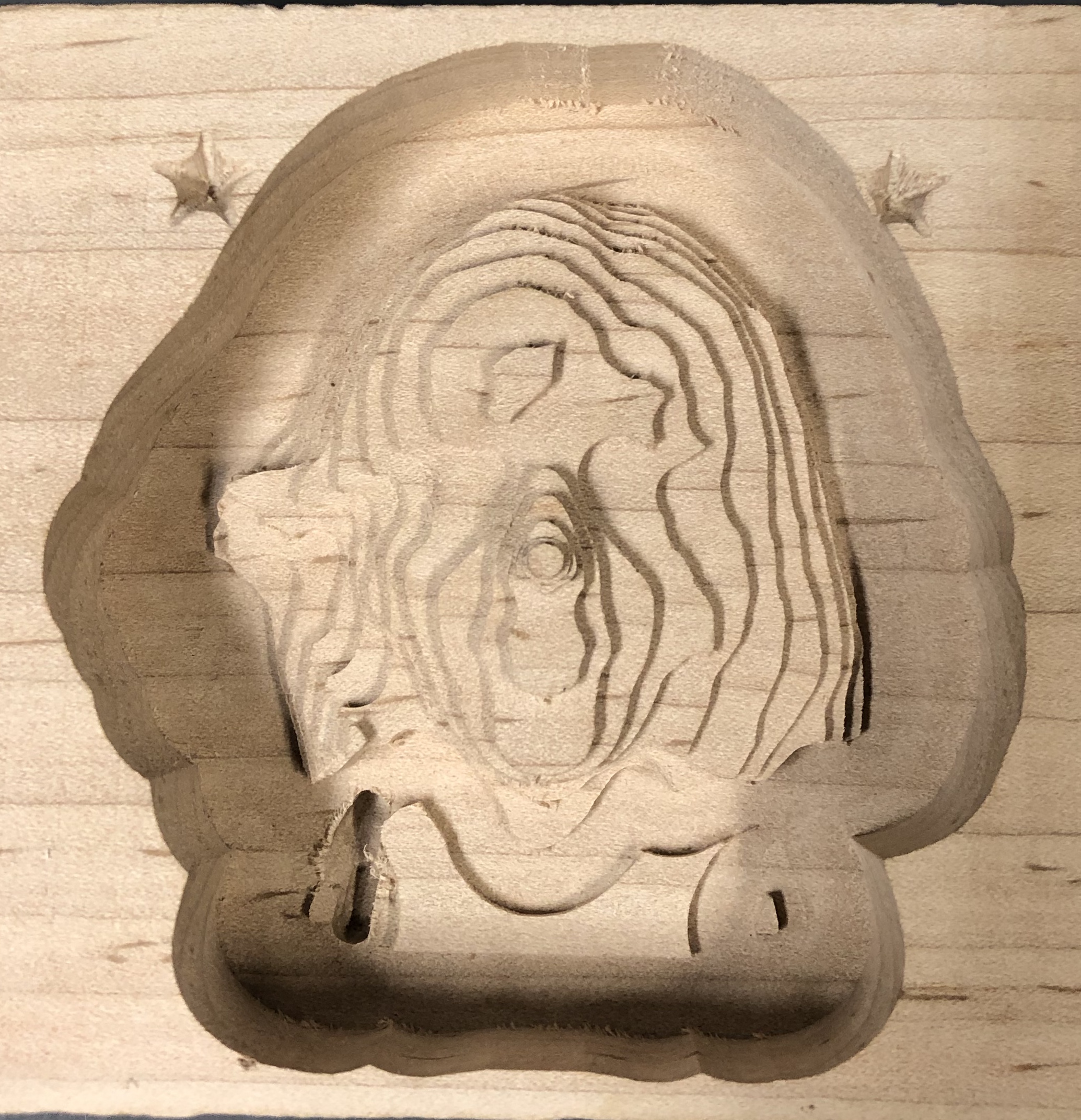
- 3D Roughing cut: When cutting 3D model files, the first toolpath is usually the 3D roughing cut. It is used to take out the majority of material and leave a rough shape of the final product. This cut decreases cutting time and prevents wear on bits.
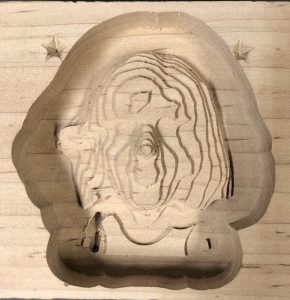
- 3D Finishing cut: After a roughing cut has been made, a 3D finishing cut can be used to go back over the material, clean up the surfaces, and add finer details.

- Setting Up 3D Toolpaths (please follow the required steps carefully)
- Make sure that the Start Depth and Cut Depth does not exceed the thickness of your material. Not doing so could result in damage of your work piece and the machine.
- Select the correct tool according to the material type and dimension of your piece. **Do not change the tool presets
- For 3D roughing toolpaths, select an endmill bit
- For 3D finishing toolpaths, select a ball nose bit
- Check to make sure that there is Machining Allowance of 0.01 inches.
- Make sure you add a Ramp Plunge Move of at least 2.0 inches.

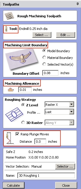
NOTE: To ease tool strain, we recommend utilizing a distance ramping of at least 1″.
- Export toolpathing

- Make sure you save the toolpath as a Shopbot .sbp file
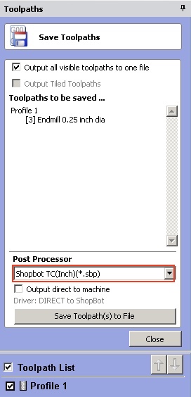
NOTE: You can change the order of your toolpaths by simply dragging them in the “Toolpath List”
Next Steps:
Previous Steps: