Category: Blog Posts (Page 14 of 15)

Summer Update: Coffee Table

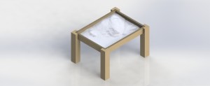
This week was spent finalizing materials and specs for the Tufts coffee table. Each component of the table can be seen in the Solidworks model below.

Rendered image of the coffee table

Rendered image of the coffee table

The four sides of the table have slots towards the bottom for the plywood base to fit in.

Side of table with slot for plywood base

Side of table with slot for plywood base

Then, the whole assembly will rest on the cutouts in the legs.

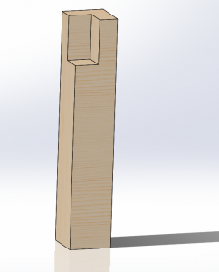
Table leg

Table leg

Once machined, the pieces of the terrain will be layered onto the plywood base and the glass top will rest in another set of cutouts in the legs.

Image_A Image_B

Shop Redesign – Pen Holder

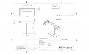
We have finished sketching out our ideations and have now moved on to creating our prototypes on Solidworks. Our pen holder model looks like this:

penholder


Before we begin the fabrication process we want to try orienting the pieces in different ways just to see if we can create a more aesthetically pleasing model. We will then begin making protoypes with whichever design we prefer. Also, we are prepared to make some changes to our model after fabricating, because the fabrication process will reveal some detail flaws that can only be noticed with the physical model. For example, while we have a sense of the amount of time it takes to build this, actually building it will obviously give us a better time approximate and we can make changes on the design depending on whether it takes too long or too short to build. Fabricating will also give us a better sense of material cost and if the structure will have proper weight distribution and will stand sturdy and upright.

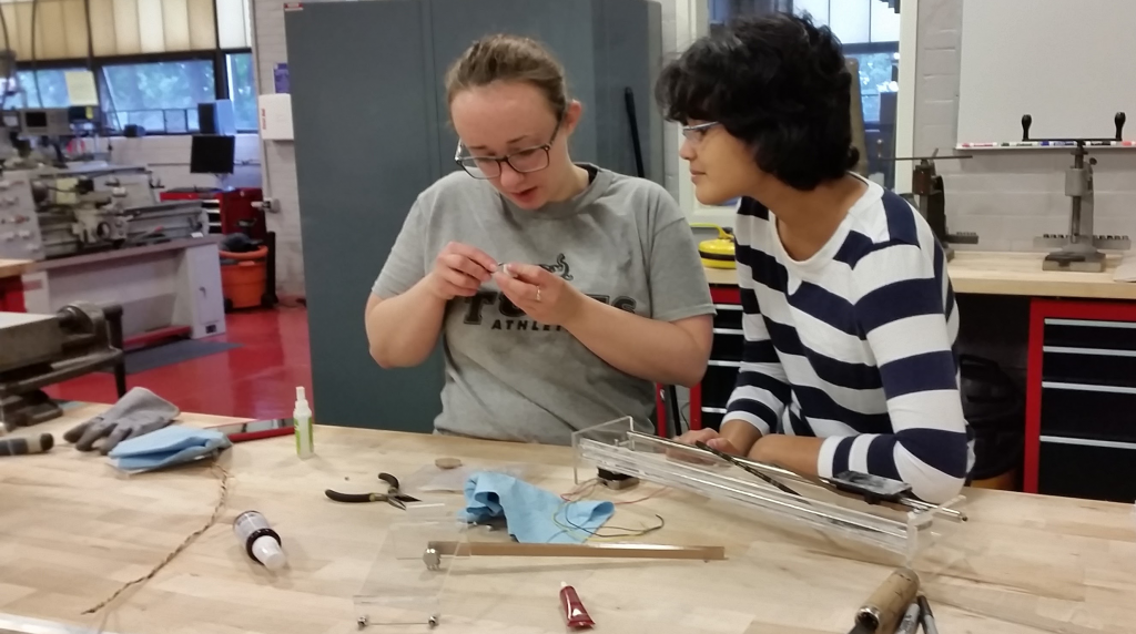
A few things to mention with this design are that we intend to use the DIWire machine to create the support mechanism which directly suspends the pen. We spent time working with the DIWire machine to figure out the minimum segment length needed for a bend in the wire and the maximum angle that the wire can bend. We discovered that there needs to be at least approximately 3/4″ of material between two bend points and the maximum bend angle is roughly 55 degrees. This knowledge was helpful because it allowed us to draft a better and more precise model that fit the maximum parameters of the DIWIRE.

In addition, we spent time making different configurations of this model on Solidworks. By that, we mean that we uploaded the same exact parts into an assembly but tried different rearrangements of those parts. We are still working on making the second configuration of the pen holder, as it has taken some time to learn the nuances of Solidworks, so we aren’t able to upload a drawing on this post  but the other model essentially deals with rotating all of the aluminum 1/4″ stock pieces 90 degrees so they lie horizontal on the main support bar, instead of vertical. We liked this design feature, and we will continue forward with the design we prefer or we may even just fabricate both models to compare.

Shop Training Redesign – Picture Frame-

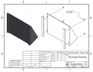
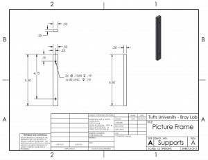
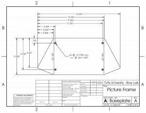
One of the leading contenders for new shop training project was a picture frame. These drawings are a first pass at designing a picture frame that could be built with the yellow zone tools. It consists of a bent aluminum sheet frame with two aluminum bar stock supports on the front; the picture is inserted by sliding it under the supports and then tightening them down to secure it.

Cost will possibly be a major issue with this design, with initial estimates putting it at more than 8 times more expensive than the wall hook. This extra cost is mostly incurred due to the expense of aluminum sheets, so next steps are to brainstorm ways to cut down on sheet stock usage and then start prototyping.
frame_drawings_rev02_Page_1 frame_drawings_rev02_Page_3 frame_drawings_rev02_Page_2

Shop Redesign Ideations

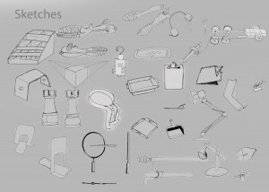
After reviewing the sketch pages, our team decided to move ahead with three concepts for a new shop training project – a pen holder, model car, and picture frame. The pen holder has a lot of room for design capabilities, and uses an appropriate amount of material for a training project, involves the use of all yellow machines plus potentially the use of the DI Wire Bender, and is practical for a college student. These qualities made the pen holder a leading candidate for fabrication as a training module. The model car, on the other hand, will probably take longer and involve more parts, but adds an element of fun and therefore more excitement. There is also a lot of room for extra design features for the car project, such as building a ramp, racing the cars, and posting the results on a leader board, or building a type of ripcord or torsional spring feature to launch the cars forward. The excitement of the car may be attractive to students, especially considering that one of the biggest problems with the wall hook was that it was boring. Lastly, the picture frame is another practical design that can be built to involve the use of all machines and is also slightly more exciting than the wall hook. However, the excitement that comes from the picture frame doesn’t come from the “fun element” like the model car, but rather from the design’s practicality. The other big problem with the wall hook was that it couldn’t be used in a dorm room. We figured that our new designs had to be either fun or practical or both in order to draw more interest in using the shop.

The next step was to ideate and create different designs for each of the concepts. Unlike for sketching, which was done on generic 8.5″ x 11″ paper, we used big sheets of paper to draw out our ideations. The goal here was to tune our concepts so they can be modeled and built well in the shop. Therefore, we put an emphasis on understanding the dimensions of the materials that the students will be working with, so we could better visualize and create ideations of our concepts that could be realistic training projects. We spent a lot of time drawing, but we also spent a lot of time discussing and building off each other’s sketches. We also wanted to brainstorm features that went outside of the realm of the yellow zone tools to add more flare and interest to the projects, while being careful to not stray too far away from the main objective of shop training. For example, we sketched out ways we could incorporate wire bending into the structure of the pen holder, or laser cut acrylic for the picture frame or bonus materials (axles and wheels) in the model car. However, as mentioned previously, it’s important to not make the project too intimidating because most of the students who are fabricating these projects probably have never spent any previous time in the shop.

To help with our ideations, we also made a trip to Toys R Us to do some “advanced research” which involved buying and ultimately taking apart some model cars. The goal was to understand some of the more advance features of the car and to get a better sense of how we could model these features in the shop. We had a good time in the store, retrieved some heavy data from our research, and Ben even recognized some of the products he helped design. We ended up buying a few different car models, and each model had a different acceleration mechanism. Two models had a wind back and release feature meaning that when the car was rolled backwards it would propel forwards upon release, three models had a ripcord design, in which a grooved, plastic, cord would be inserted into a rotating gear that was fixed to the car’s wheel and when the cord was pulled backward, the wheel would spin forwards. The last car model had a charged acceleration method that worked by rolling the car a few times forward while keep it secure in hand, and then letting it go after a significant amount of torque was built up.
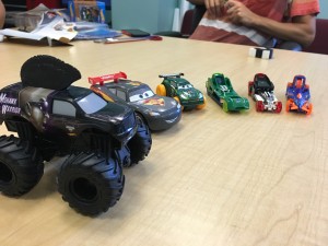
IMG_3201

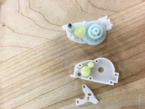
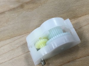
We took apart the models and examined the interior. We first looked at the two “Cars” models, which both featured the wind-back design. After breaking off the exterior shells we noticed that both models have a very similar design for their respective systems. They both featured a gearbox system that attached to a torsional spring. A gear was connected to a torsional spring on end and attached to more gears that ultimately connected with a fixed gear on the axle. When the car was released, the torsional spring would release, spinning the gear rapidly and propelling the car forward.
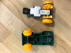
IMG_3203 IMG_3210 IMG_3214

Above, we can see the gearbox system that is used to accelerate the car. The blue gear connects to the torsional spring and the green gears attach to the smaller blue gear which is fixed on the car’s rear axle. It is worth mentioning that the other “Cars” model had a nearly identical gearbox.

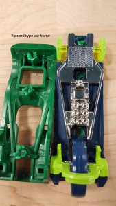
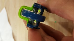
The next models we observed were the ripcord “Hot Wheelz” cars. These cars had a grooved gear attached to the rear axle. The ripcord would insert into the slot between the gear and frame, and when pulled back it would spin the back wheel, moving the car forward.
Zipcar frame20160713_154738


The car had a three wheel design, with a much larger wheel located in the rear of the frame. This design is something we could see ourselves emulating, because it would be relatively easy to create the gear and ripcord with the 3D printer and laser cutter and it would be a cool bonus feature to have the car accelerate without just simply pushing it forward. Creating the body of the car could be done with the use of all yellow zone tools so students could get all the appropriate training, which is the main objective of the project. This was an idea we liked, and definitely wanted to ideate further with the ripcord design in mind.

Today, there is still work to be done to create the final models of each design so they can be designed in CAD and we can begin prototyping them. This week will be spent doing just that – designing our models on Solidworks and hopefully we can begin fabricating them in the shop. Once we actually fabricate each model we will have a much better idea of the amount of materials, rigor, and time needed to build each project.


Summer Update: Coffee Table

After successfully modeling the Tufts campus in Google Sketchup and Autodesk 123D Make, I decided to test out different programs to split up the .STL file into sections that would fit on the ShopBot CNC Router.

The final .STL shown in Autodesk 123D Make

The final .STL shown in Autodesk 123D Make

The complex file was made up of too many faces to be manipulated in Solidworks, Autodesk Fusion360, or Meshmixer. So, instead of trying to take the one large file and split it up into smaller sections, I decided to go back to Google Sketchup and Autodesk 123D Make and create two smaller .STL files that would eventually be matched together.

Northern piece of the Tufts campus

Northern piece of the Tufts campus


Southern piece of the Tufts campus

Southern piece of the Tufts campus

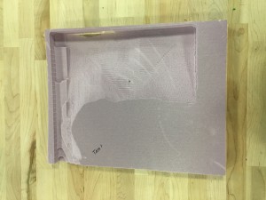
With the two .STL files exported from Google SketchUp and imported into Autodesk 123D Make, I was able to set the material settings to be the same such that both .STL files would be sliced at the same height. Each file will have a base slice that includes most of the topography, topped by a second slice that includes only the highest points of elevation on campus. The first practice piece, shown below, helped sort out a few issues here and there with the machine setup, bit choice, and toolpaths.

First test piece of slice 1

First test piece of slice 1

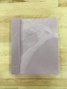
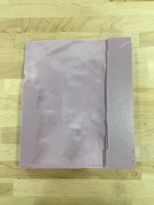
After fixing those issues I was able to successfully make the two base slices of the Tufts model at a 1:3 scale.

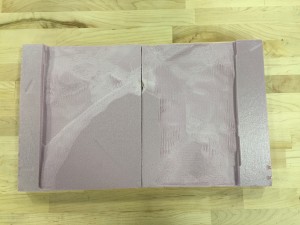
Northern part of Tufts campus model

Northern part of Tufts campus model

Southern part of Tufts campus model

Southern part of Tufts campus model


The two halves matched together

The two halves matched together


Summer Project Update: Coffee Table

The following link will take you to the brand new CNC Router page on the Bray Lab website: https://sites.tufts.edu/bray/theshop/shopbot-cnc-router/

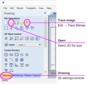
By combining the detailed information from the CNC Router’s google site with tips and tricks I have learned over the past few weeks working with the machine, I was able to organize the information and present it in a user-friendly manner.  Many photos and diagrams, like the one pictured below, were included to help new and returning users locate obscure buttons and commands.

Drawing crop

While trying to explain a chain of commands in writing can be precise and descriptive, pictures help break up the text and make the text clearer. All of the information on the Shopbot CNC Router was split up into different sub pages, to help locate information more quickly. If a user just wanted a refresher on what each kind of toolpath did, they could simply click on the ‘ShopBot File Setup’ page and skip to the ‘Toolpathing’ section. 

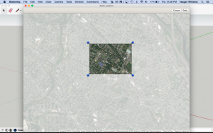
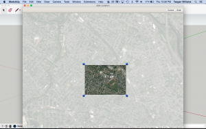
With the new section of the website completed, it was back to the coffee table. For the past couple weeks, I have been trying to find a method that would allow me to create a topographic .STL file of the Tufts University, Medford campus. My first google search brought me to a website called “Terrain 2 STL” which, as the name suggests, creates an STL file of whatever land you section off in a Google Maps window. However, the smallest size you could make the selection window included sections of Medford, Somerville, Cambridge, and Arlington, making it very difficult to decipher which large bump on the map was Tufts. With that option exhausted, I researched other methods of generating .STL files of land. One of the methods I found suggested creating a .TXT file with the latitude, longitude, and elevation coordinates of various point round Tufts and importing them into Solidworks to make a “point cloud.” While the Youtube tutorial of this process created a clear, smooth solid of the terrain, I was left with hundreds of triangles that produced a stalagmite-looking object. I scoured Solidworks forums and maker space blogs searching for a way to create this file, and clearly I was not the only person eager to 3D print or CNC their own topography. Thankfully, this morning a new method involving Google Maps and SketchUp was suggested to me. With some quick internet searching, I found this tutorial, followed along with only a few hiccups, and was able to generate an accurate, detailed .STL file of Tufts.

The final .STL shown in Autodesk 123D Make

The final .STL shown in Autodesk 123D Make

Since the model will be about 24″x36″x4″, it will need to be cut in sections on the ShopBot CNC Router. Autodesk’s 123D Make is a versatile CAD software that will slice a 3D model using various slicing techniques.

In the upcoming week, I hope to start practicing making this piece on the XPS foam, finding the optimum slicing technique, and researching more joinery methods with which to assemble the table!

Revitalizing Malden High School’s Workbenches

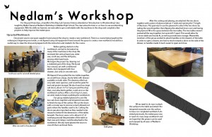
One of the largest engineering spaces currently missing from the Tufts campus is a student-accessible wood shop. But over at Malden High School, professors and Tufts students are working to create a fully-equipped wood shop/makerspace in Nedlam’s Workshop, a mere ten-minute drive from Tufts. Several of us spent the last few days there learning about the tools and working to improve the space, cleaning it up and creating new and improved work spaces around the shop. My team’s particular focus was the shop’s four solid maple workbenches, each of them a beautiful butcher’s block work surface covered in years of varnish, paint, and grime. Our task was to clean up and stabilize the decrepit worksurfaces and solidly remount the woodworker’s vices loosely hanging off each bench.

A quick experiment with a planer and then handheld sanders revealed that the built-up coatings were more than a match for our tools. The layers of varnish quickly clogged sandpaper, and hidden nails blocked progress with the planer for fear of chipping the blade. But a much easier solution quickly presented itself: flip the table tops over. Four easily-removed bolts secured each top to the base, and with them out of the waywe found bottom surfaces in near-mint condition. Some wood filler, scrapers, and a little bit of sanding took care of years of holes and gum within minutes.

Our other challenge, then, was to mount the vises. The vises had originally been mounted with lag screws, which, while solid, will (and had) eventually strip out a hole. So instead of screws, we used carriage bolts to secure the vises through the table. The bolt heads were counterbored – sunk into the tabletop so as to sit flush – and secured on the bottom with nuts and washers; additionally, the vise faces were screwed into the table face. This secure mounting mechanism will allow the hardware to be continually re-tightened whenever it loosens, something not possible with lag screws. The finished workebenches were much more solid, smooth, and easily usable – and stylish to boot.

« Older posts Newer posts »

© 2025 Bray Lab

Theme by Anders NorenUp ↑