Tension Test Machine Setup
For a Tension test, the following fixtures and components are required:
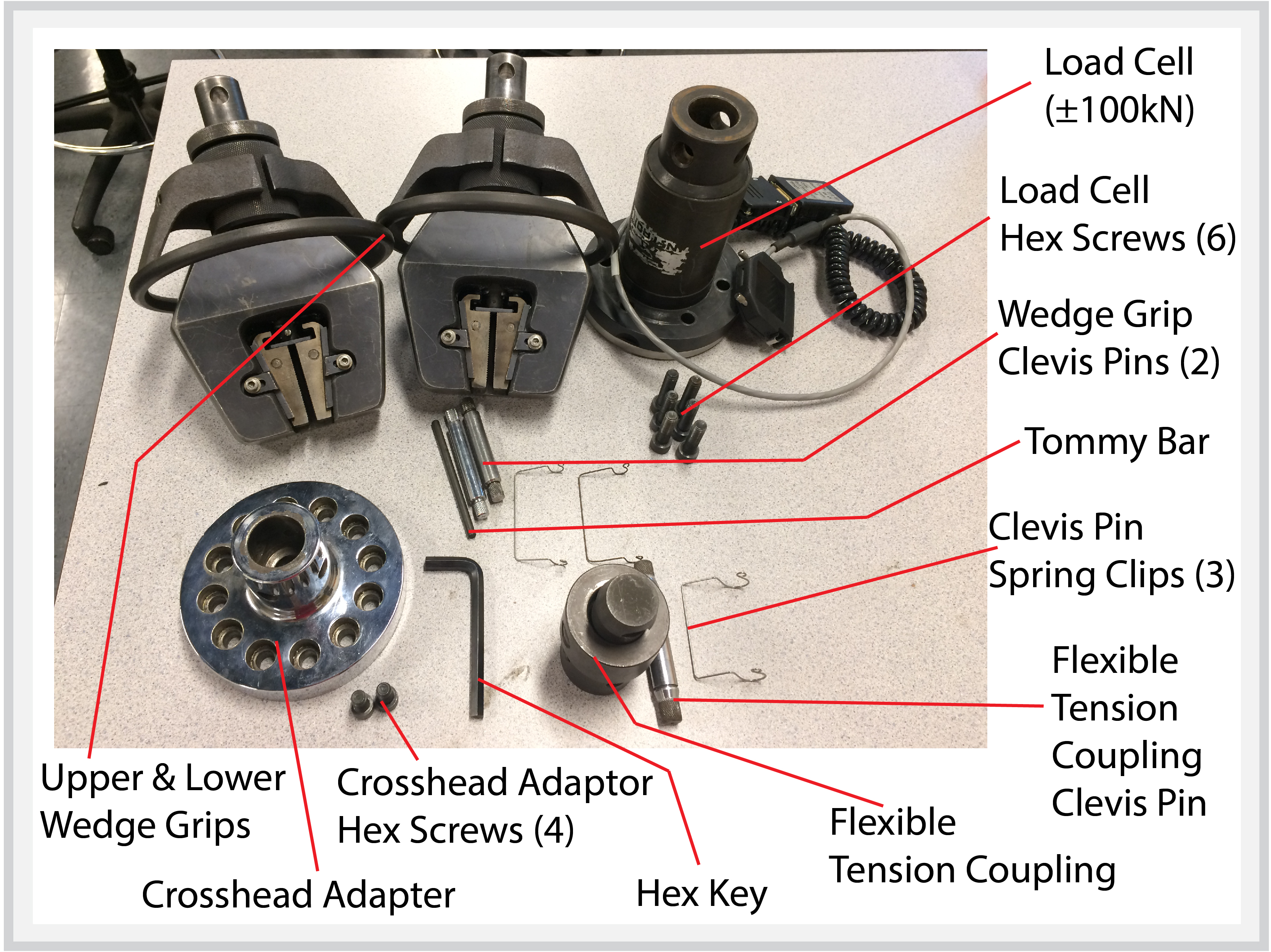
○ Load Cell (±100kN)
○ Load Cell Hex Screws (6)
○ Upper and Lower Wedge Grips
○ Wedge Grip Clevis Pins (2)
○ Flexible Tension Coupling
○ Flexible Tension Coupling Clevis Pin
○ Clevis Pin Spring Clips (3)
○ Crosshead Adapter
○ Crosshead Adapter Hex Screws (4)
○ Red Chuck Spanner Wrench [not pictured]
○ Hex Key
1. Install Load Cell
- Make sure there is no Load Cell currently installed in the Load Frame.
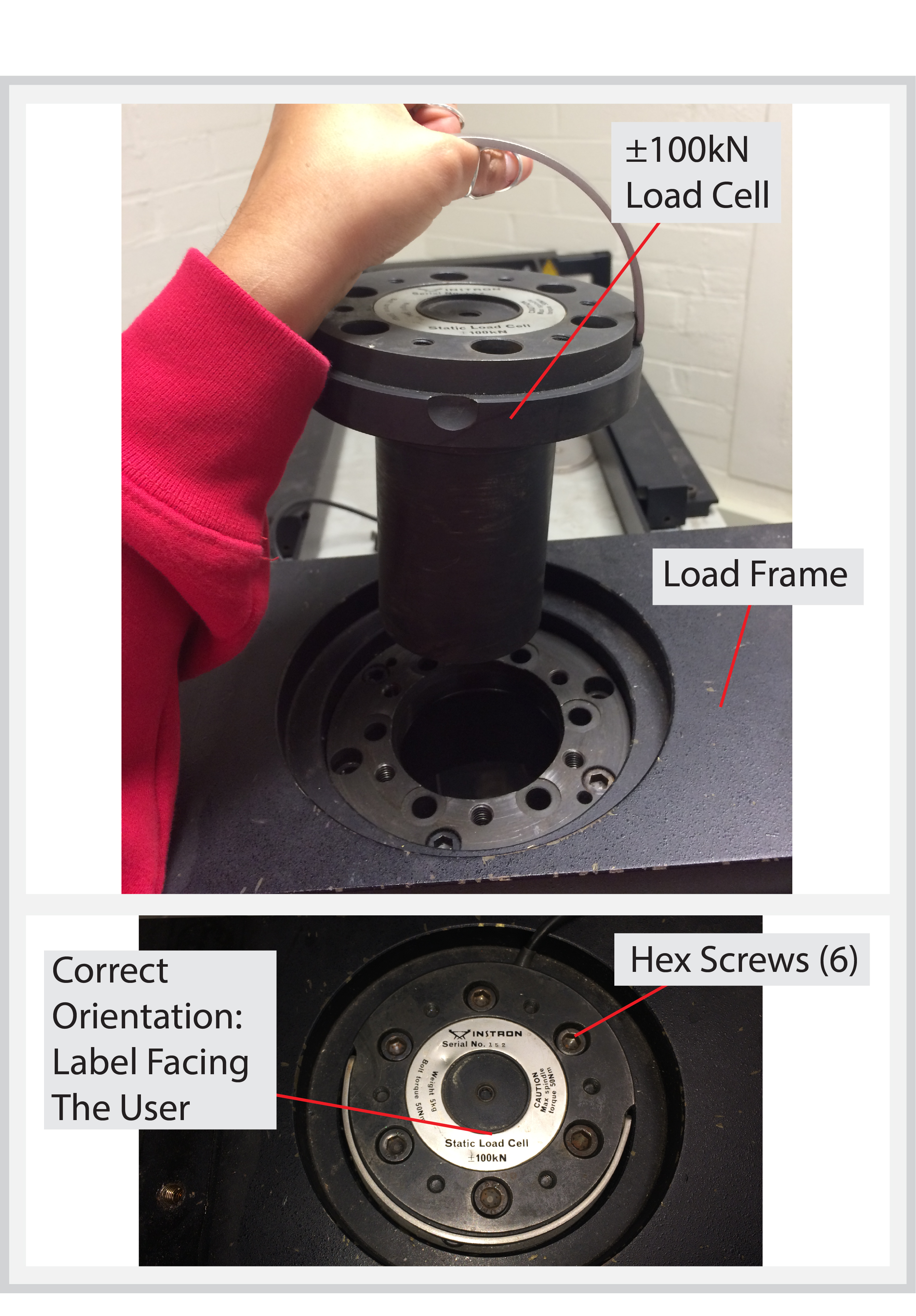
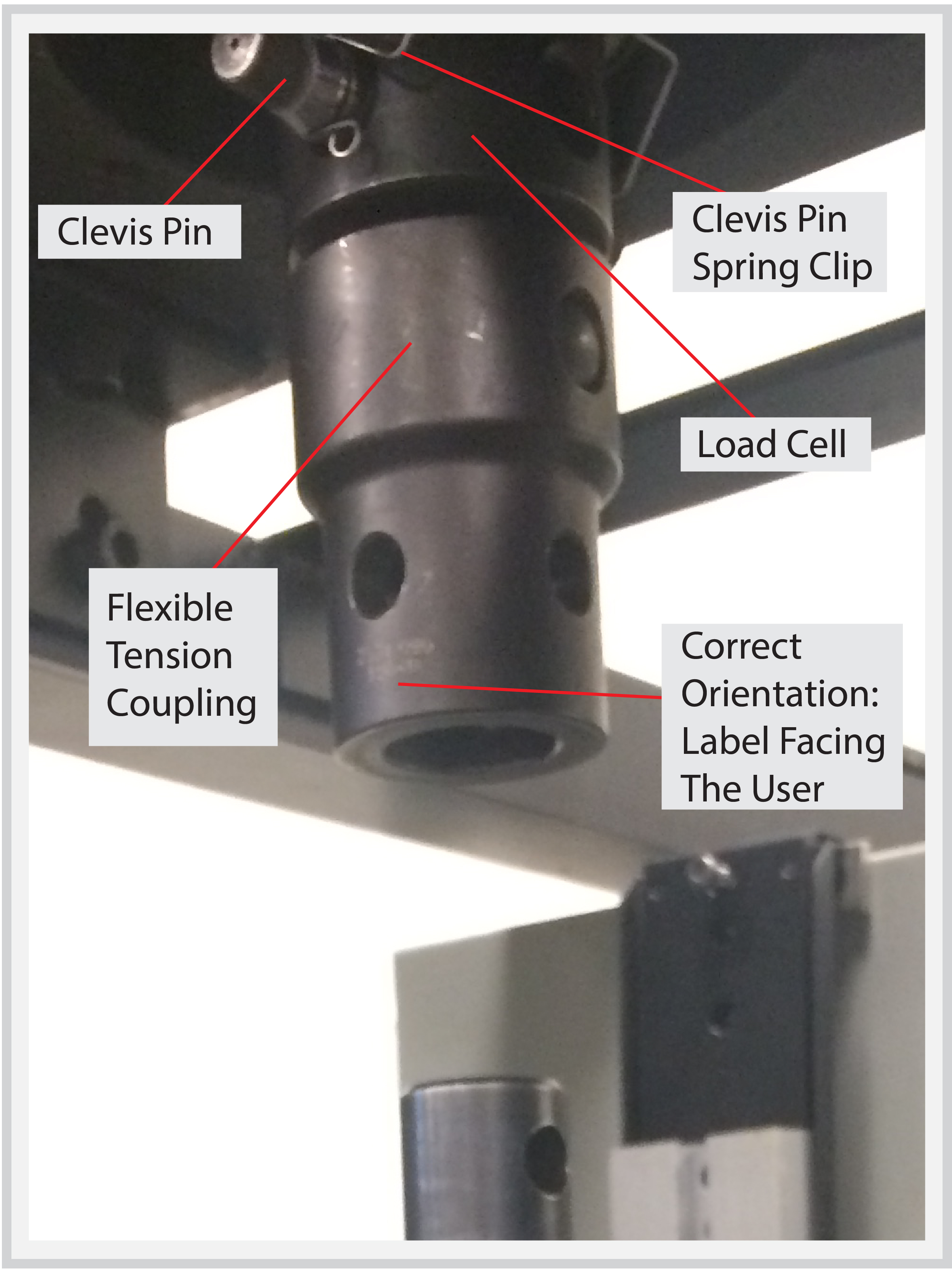
- Insert the ±100kN Load Cell into the top of the Load Frame making sure that it is in the correct orientation (i.e., the wording on the label is facing the operator).
- Attach the Load Cell to the Load Frame using 6 Hex Screws.
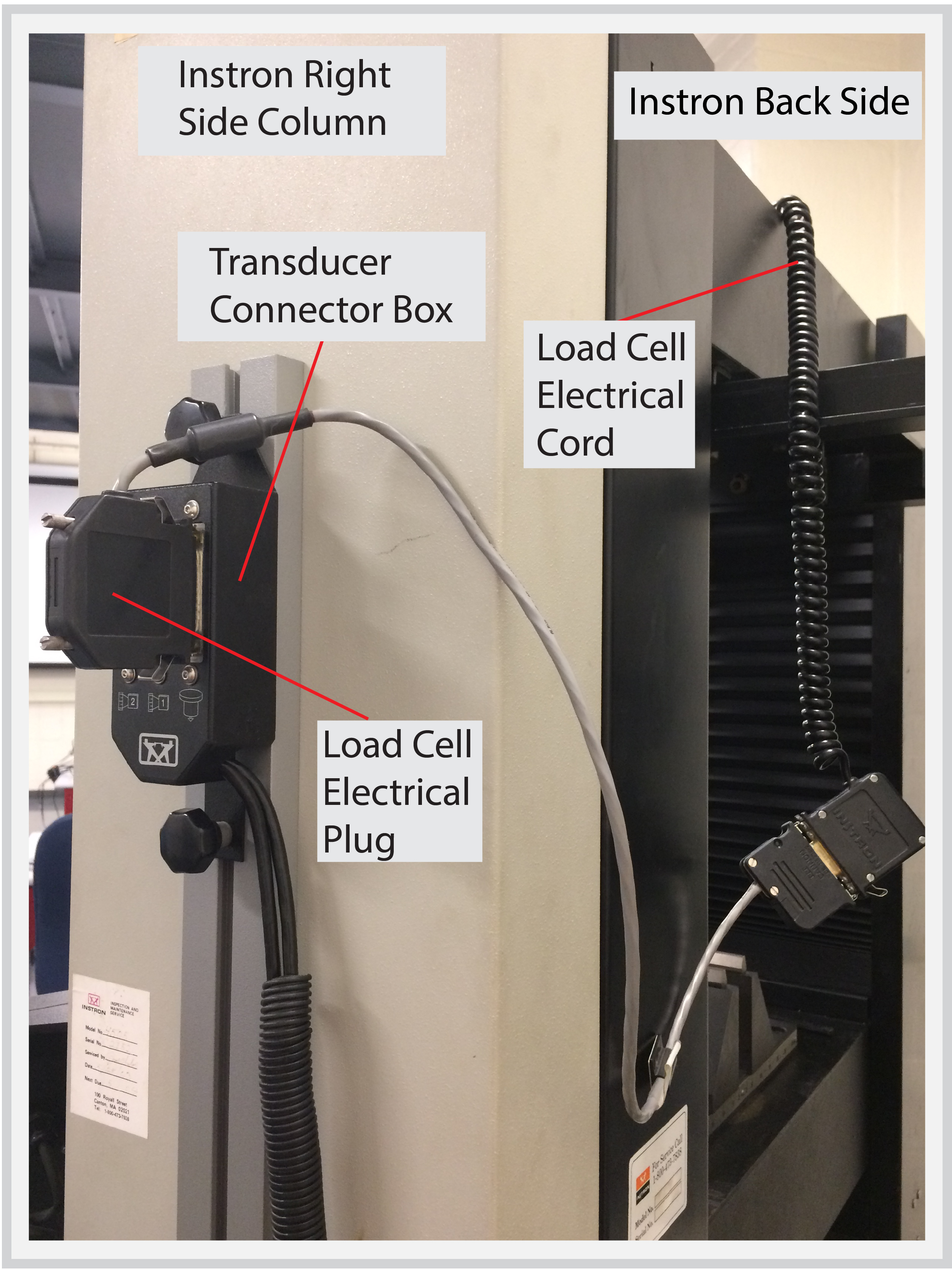
- Plug the Load Cell into the Transducer Connector Box.
- On the Desktop Computer, start up the Bluehill application software. This will enable the jogging operation of the Crosshead.
2. Install Lower Wedge Grip
- Make sure all previous fixtures have been removed from the Instron.
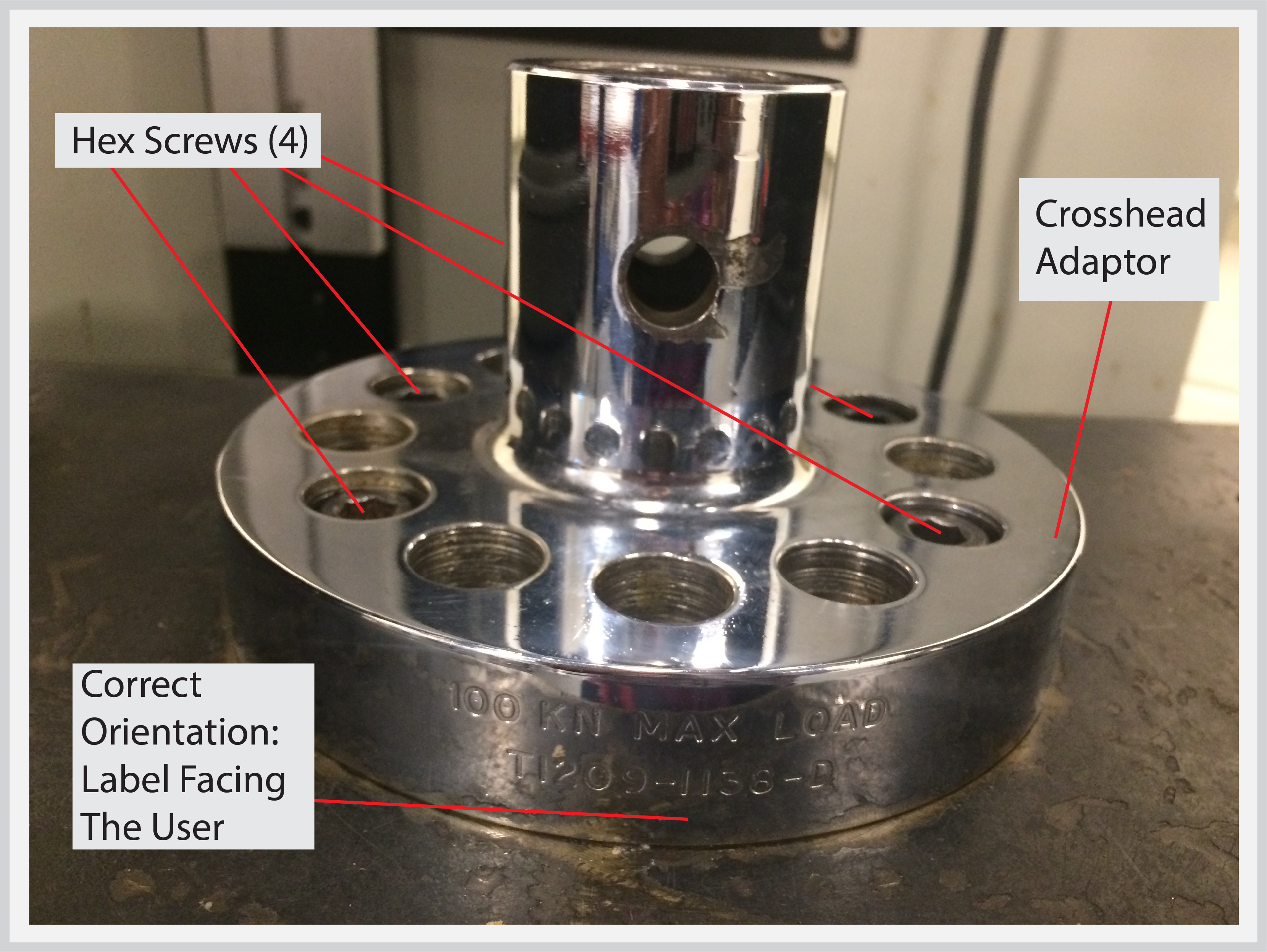
- Place the Crosshead Adapter onto the Crosshead, line it up with the screw holes, and attach the Adapter using at least 4 Hex Screws.
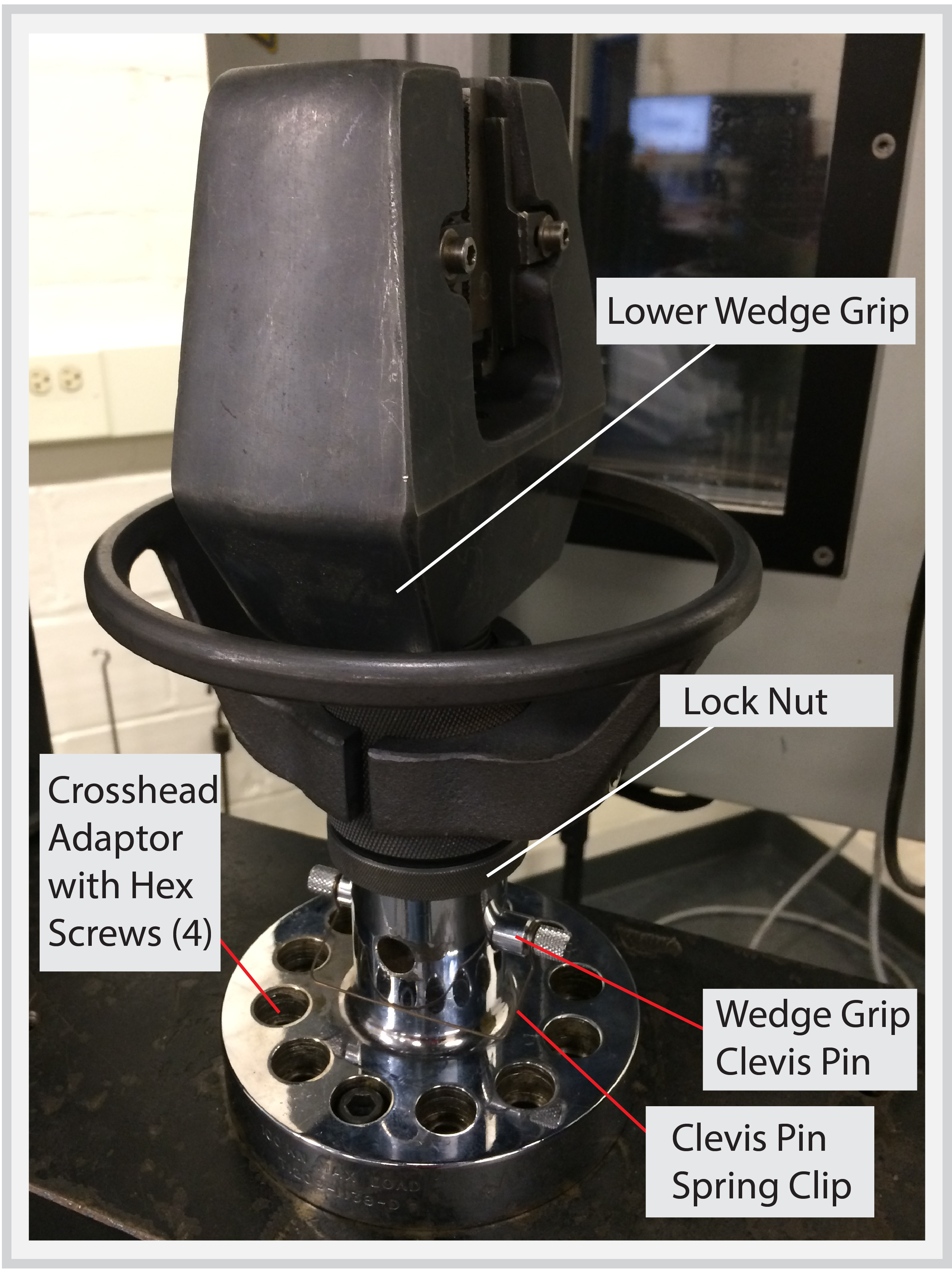
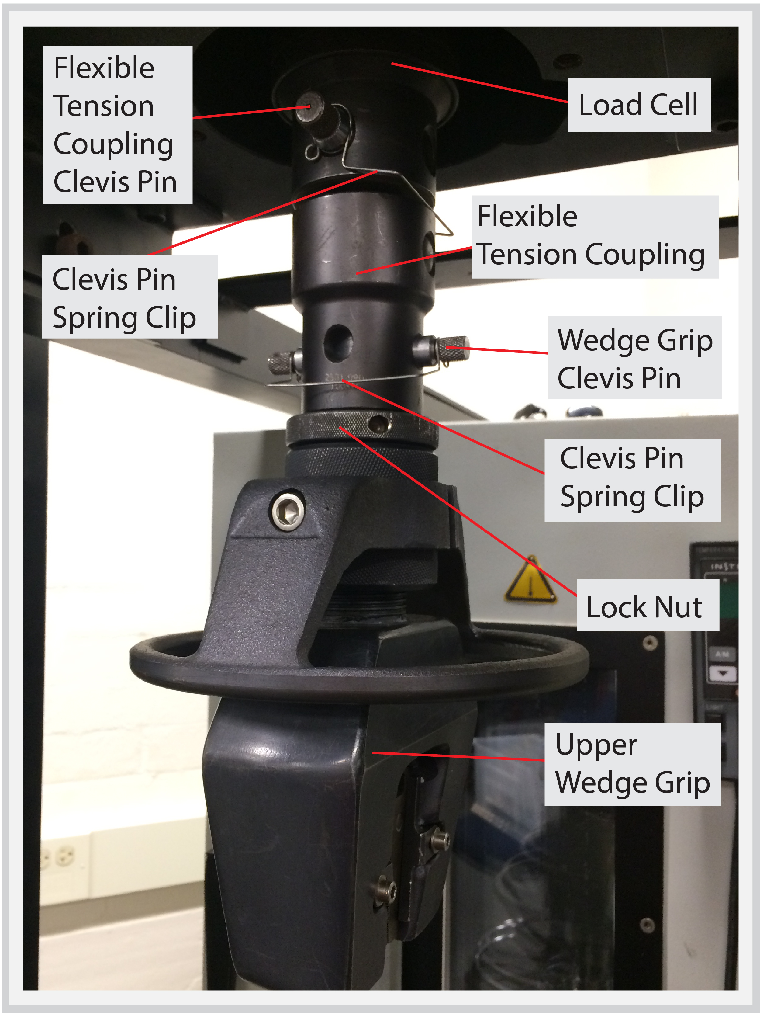
- Insert the Lower Wedge Grip into the Crosshead Adapter and secure it with a Clevis Pin.
- Use the red Chuck Spanner Wrench or hand-tighten the Lock Nut against the Crosshead Adapter
- Attach a Spring Clip to the Clevis Pin.
3. Install Upper Wedge Grip
- Insert the Flexible Tension Coupling into the Load Cell and secure it with a Clevis Pin.
- Attach a Spring Clip to the Clevis Pin.
- Since the Wedge Grips are heavy and unwieldy, it can be difficult to lift the Upper Wedge Grip up to the Flexible Tension Coupling for attachment. By carefully following the directions below, you may use the Lower Wedge Grip to carry the Upper Wedge Grip up to the Tension Coupling.
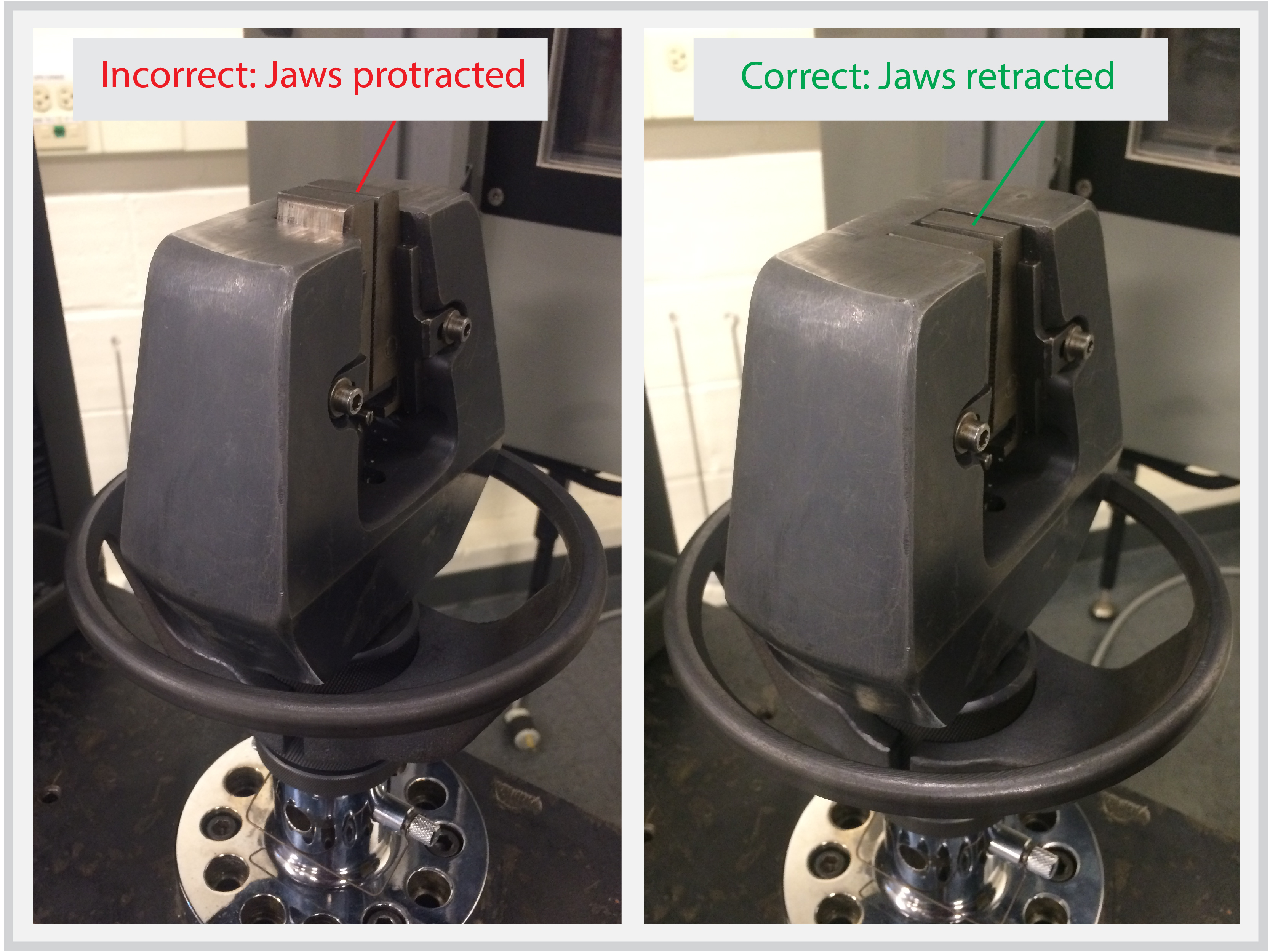
- First, make sure that the Jaws on both Wedge Grips are retracted. Loosen the vise as necessary to retract the jaws until they are flat against the wedge faces as pictured below:
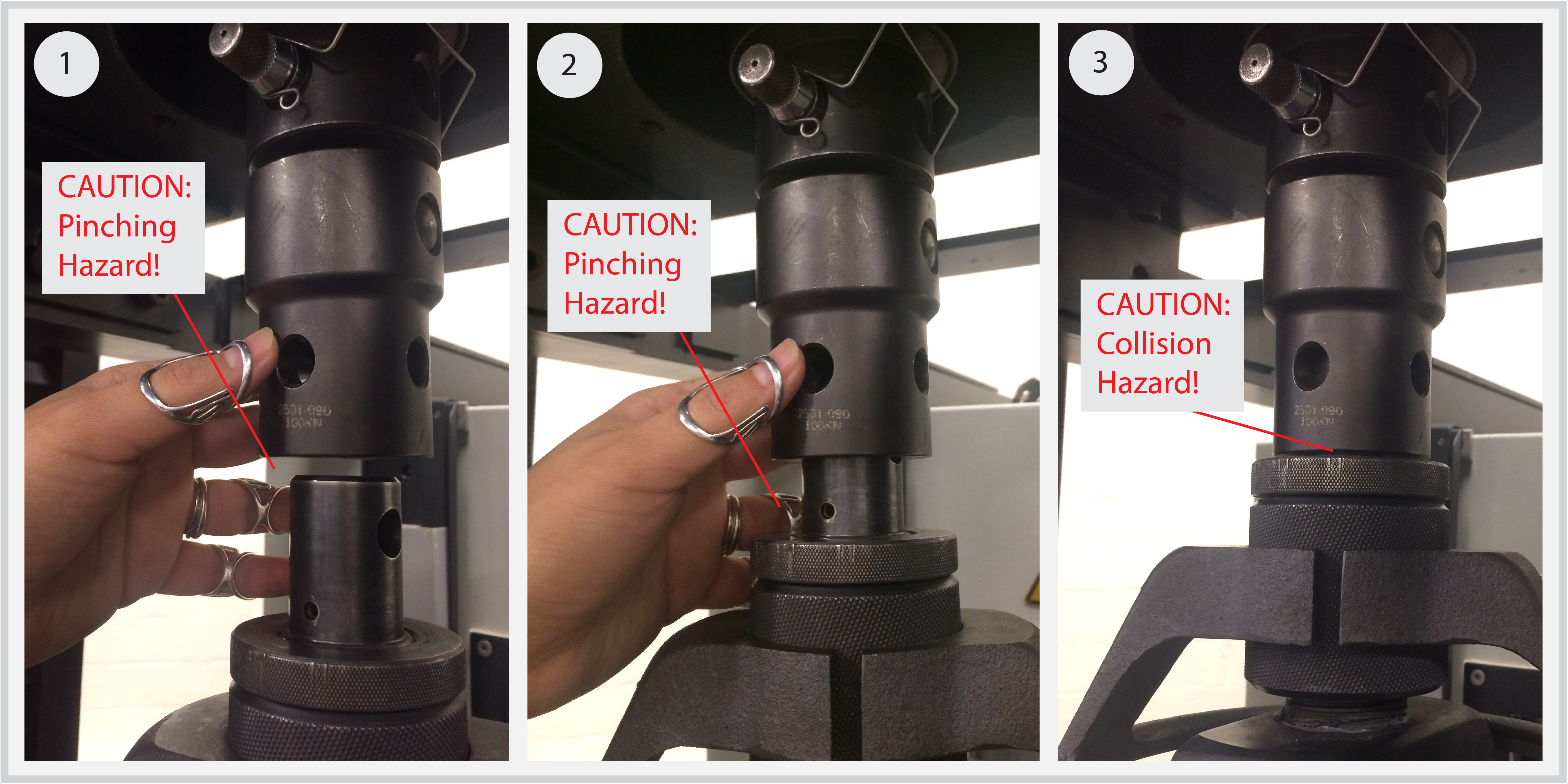
- Place the Upper Wedge Grip on top of the Lower Wedge Grip as pictured below. Note: You may need to jog the Crosshead downward to make enough room for the Wedges to sit on top of each other.
- Switch the clutch into low gear.
- Hold onto the the Upper Wedge Grip firmly so that it doesn’t slip off of the Lower Wedge Grip.
- With the clutch in low gear, slowly jog the Crosshead upward until the Upper Wedge Grip is approximately an inch away from the Flexible Tension Coupling.
- Very slowly jog the Crosshead upward while holding onto the Tension Coupling, and carefully guide the Upper Wedge Grip into the Tension Coupling until the holes for the Clevis pin line up. Note: Make sure the Upper Wedge Grip and Flexible Tension Coupling DO NOT COLLIDE!
- Secure the Upper Wedge Grip to the Flexible Tension Coupling with a Clevis Pin.
- Use the red Chuck Spanner wrench or hand-tighten the Lock Nut against the Flexible Tension Coupling
- Attach a Spring Clip to the Clevis Pin.
Next Steps:
- Tension Test: Software Setup
- Tension Test: Running a Tension Test – page under construction
