After spending the majority of the summer brainstorming, sketching, designing, modeling, and practicing the techniques required to build a table, we were able to assemble the final coffee table this week.
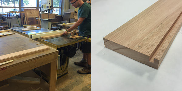
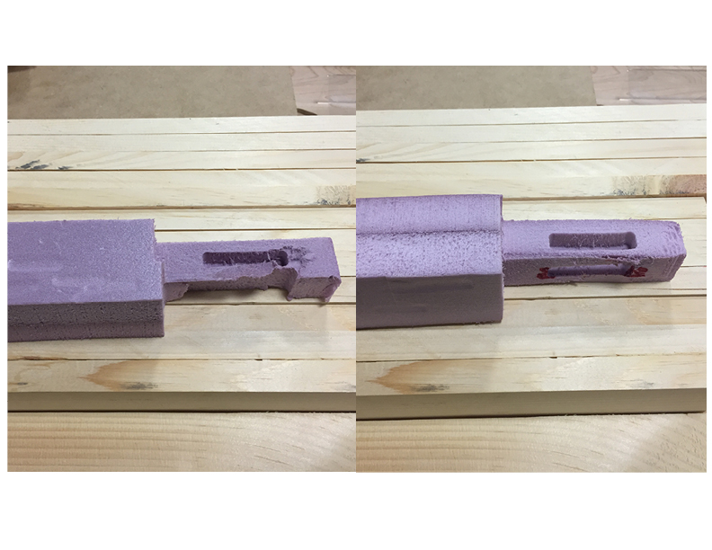
The first step in assembling the table was to mill the legs on the ShopBot. The way the legs were designed allowed me to run the same CNC program one time on each leg. To ensure that the program started and ended in the same place every time, I cut out a foam jig to clamp down on the ShopBot bed and then placed the leg in the jig.
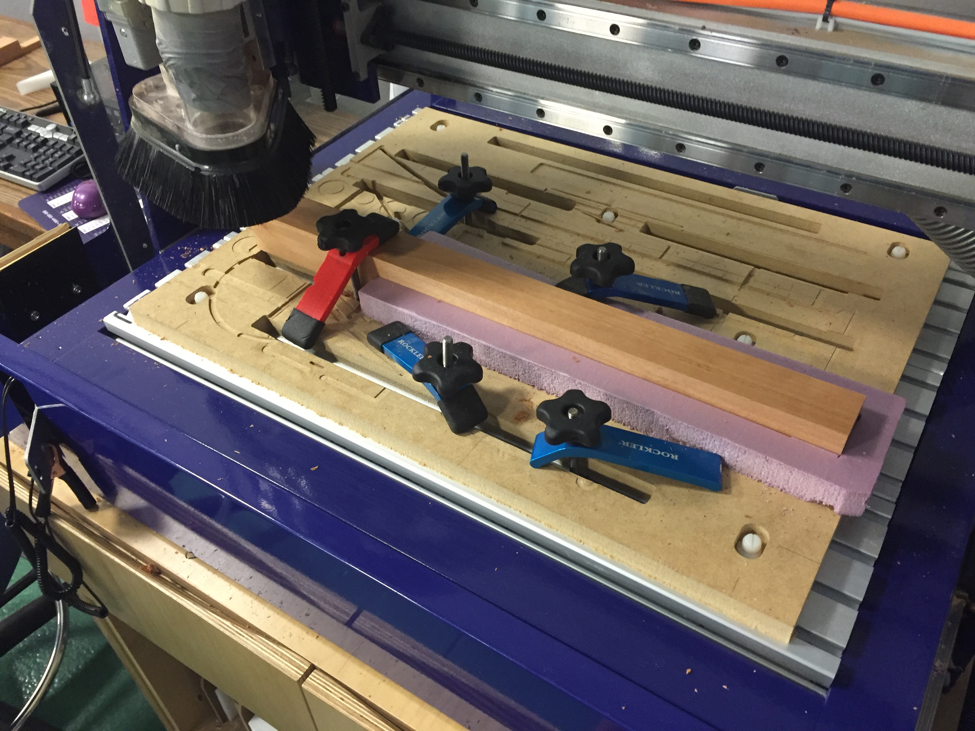
One of the legs in the foam jig
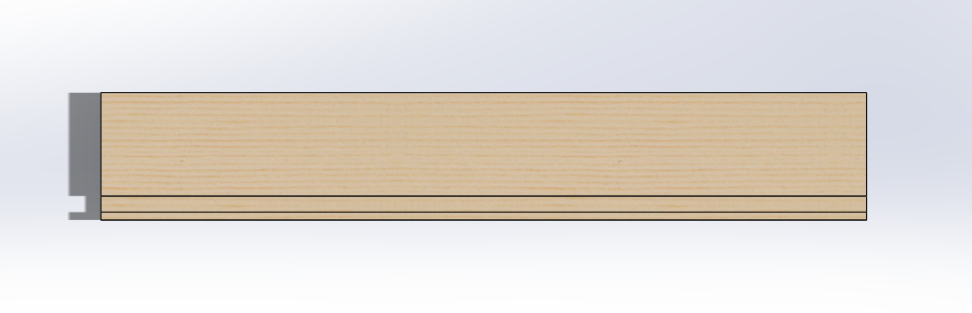
Once the leg was done being milled, I was able to remove it without moving the jig, place a new leg in, and run the same program without having to re-zero any of the axes. I used a 1/4″ end mill bit to get a flat cut for the wrap to rest on.
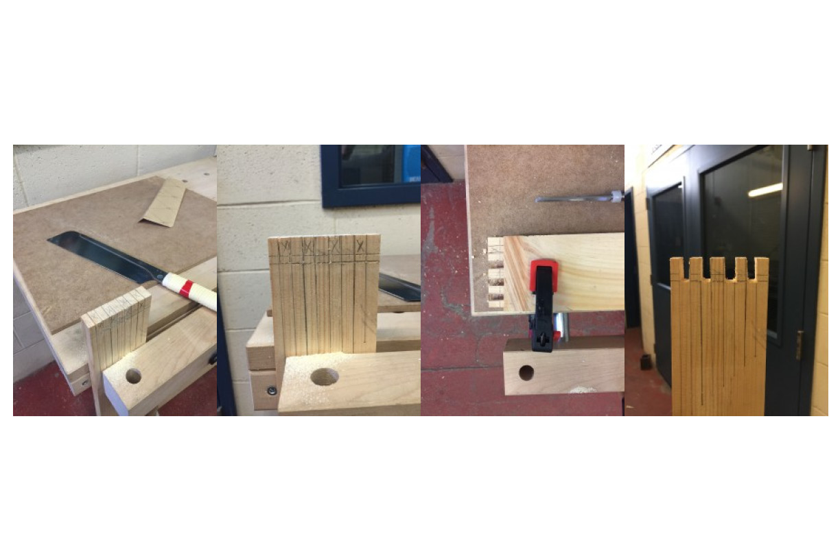
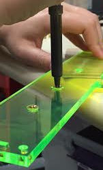
Once Ben had completed the finger joints, we were able to put the table wrap together and fit the legs in. Unfortunately, some of the legs stuck out too far from under the wrap. The amount of material we needed to take away was too much for sandpaper or a hand planer, but too little for a table saw. Thankfully, there is a planing bit for the ShopBot (seen below).
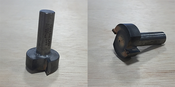
Unlike the end mill and ball nose mills, the planing bit cannot plunge
Having only used that bit once with HDPE, I was reluctant, but it was looking like our best option. I placed my legs back into the foam jig I used earlier, switched out the 1/4″ end mill bit for the planing bit, and used a .1″ pocket cut on two faces of each leg.
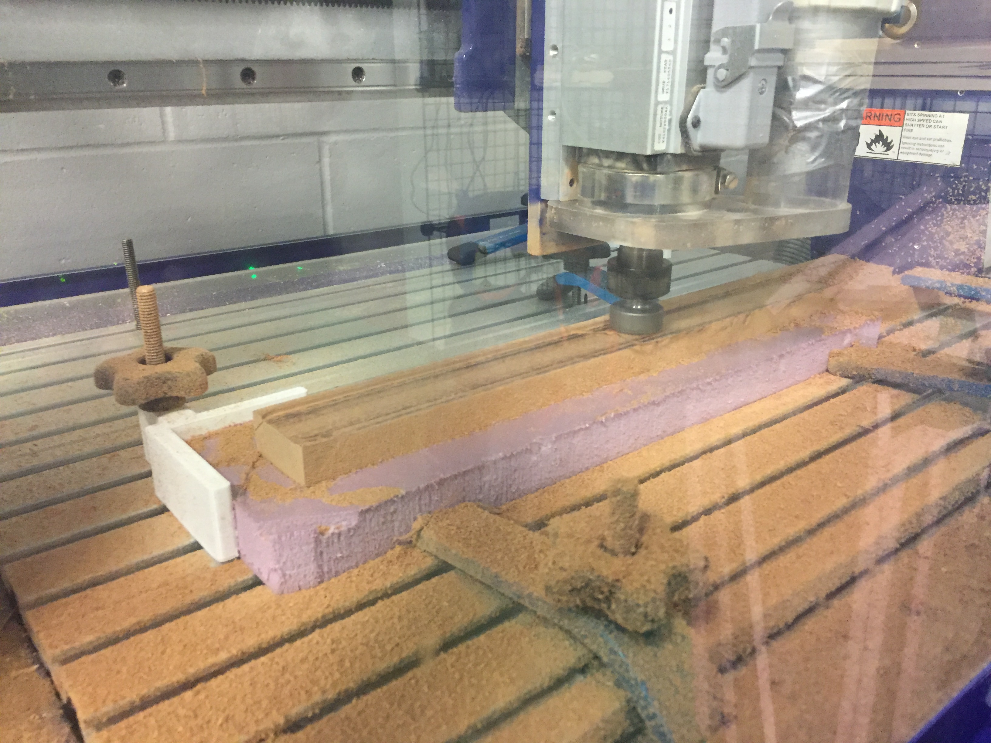
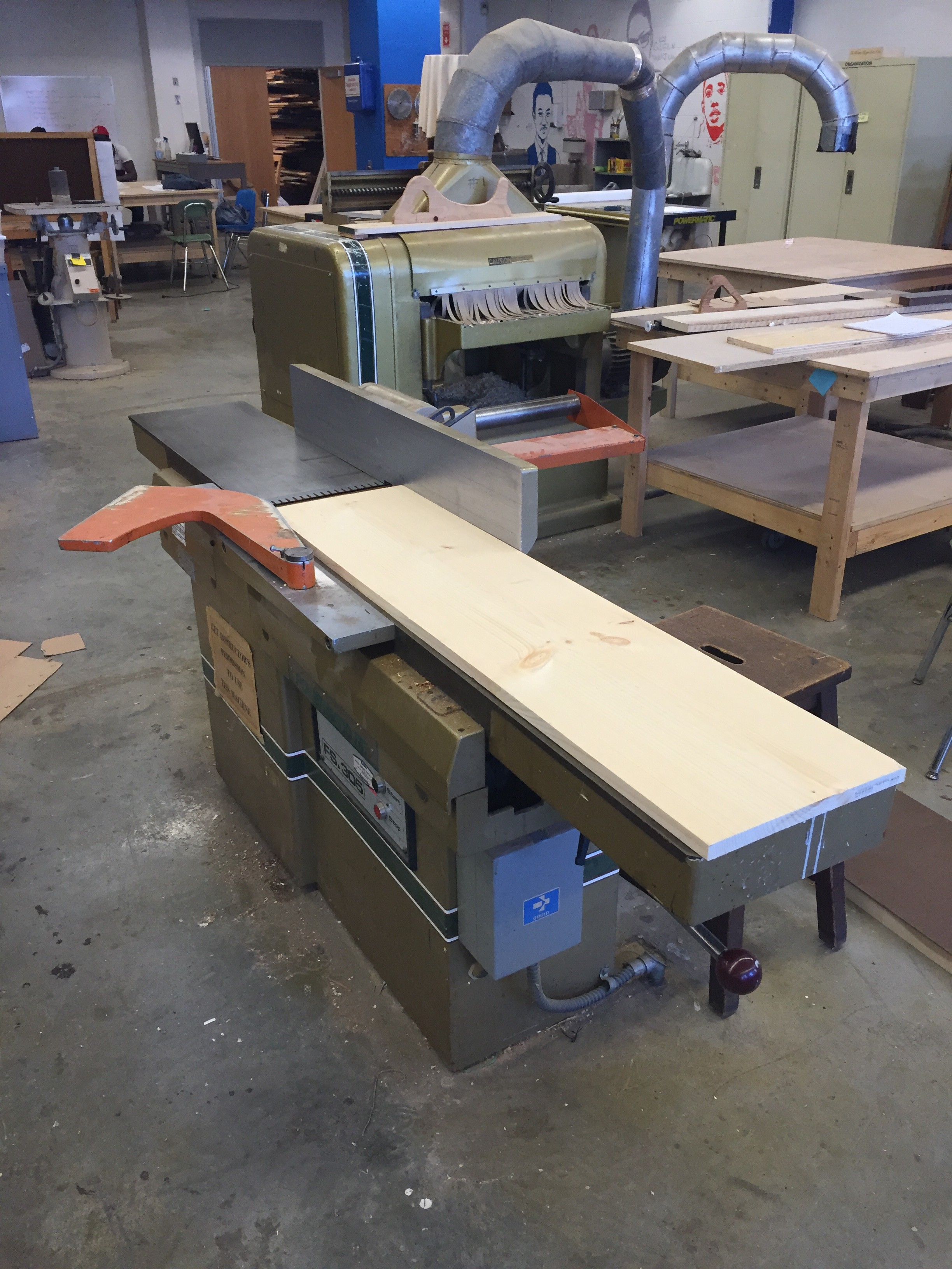
One of the table legs being planed
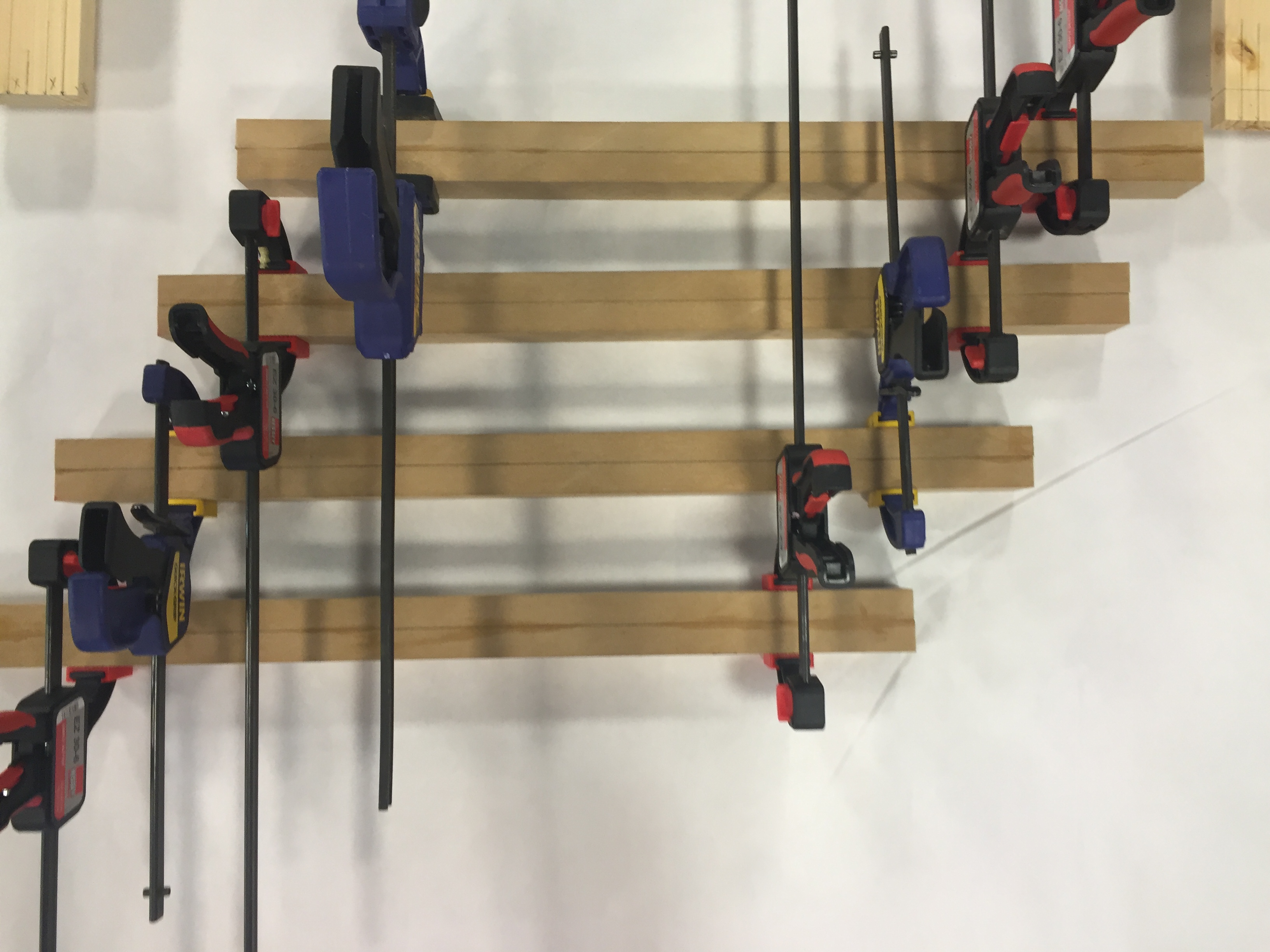
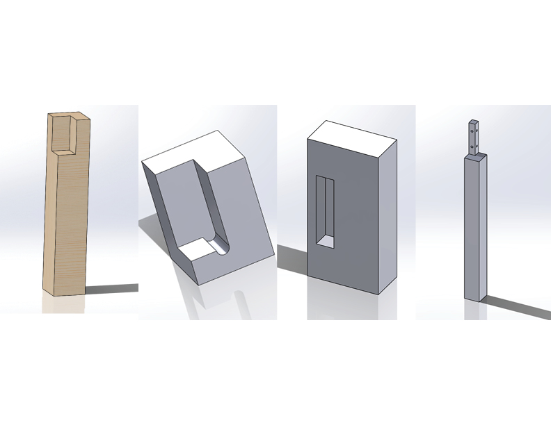
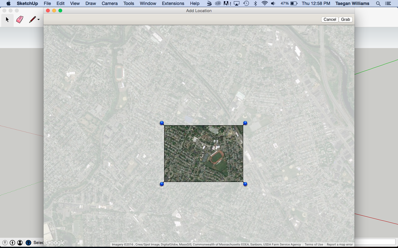
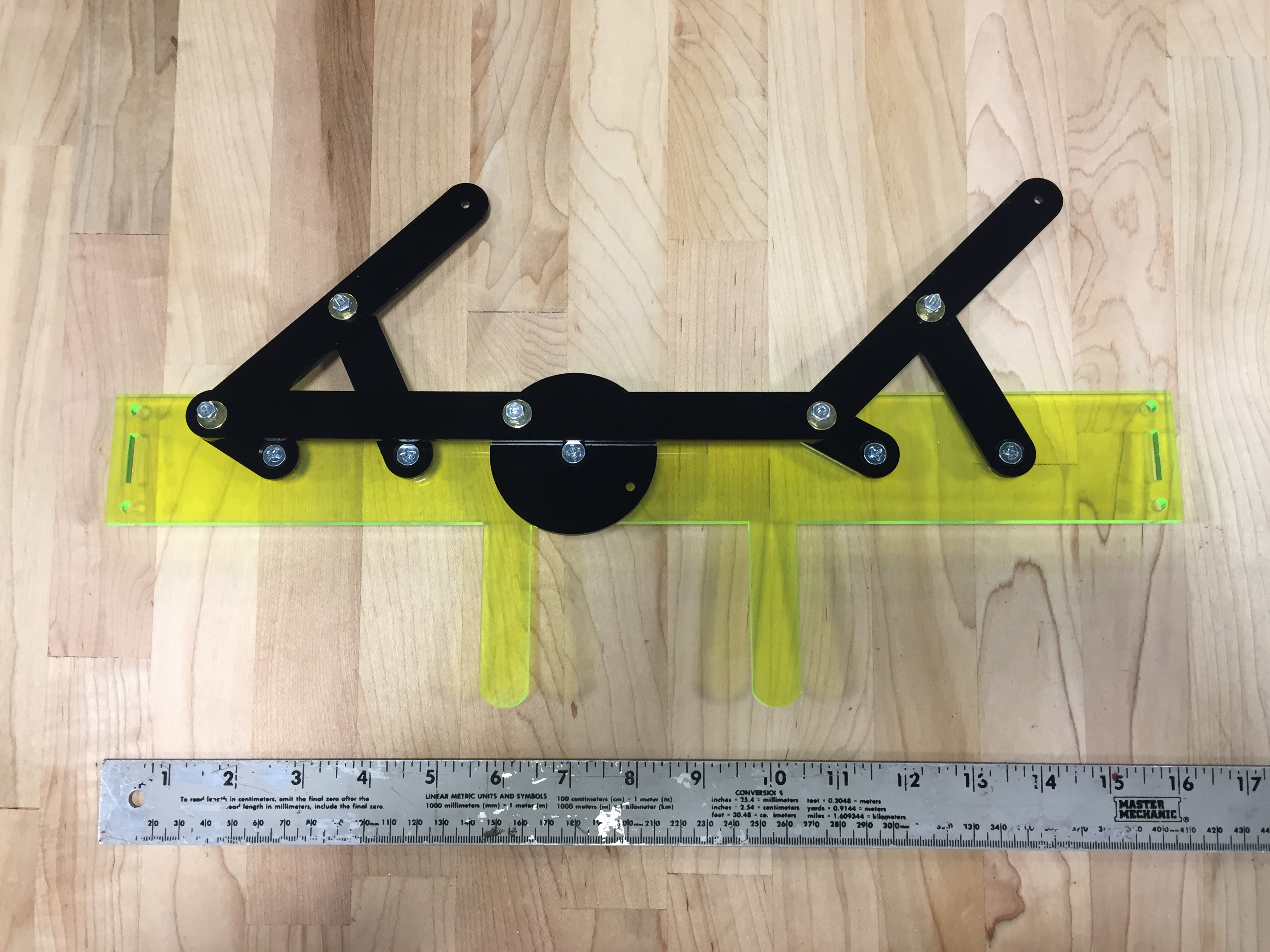
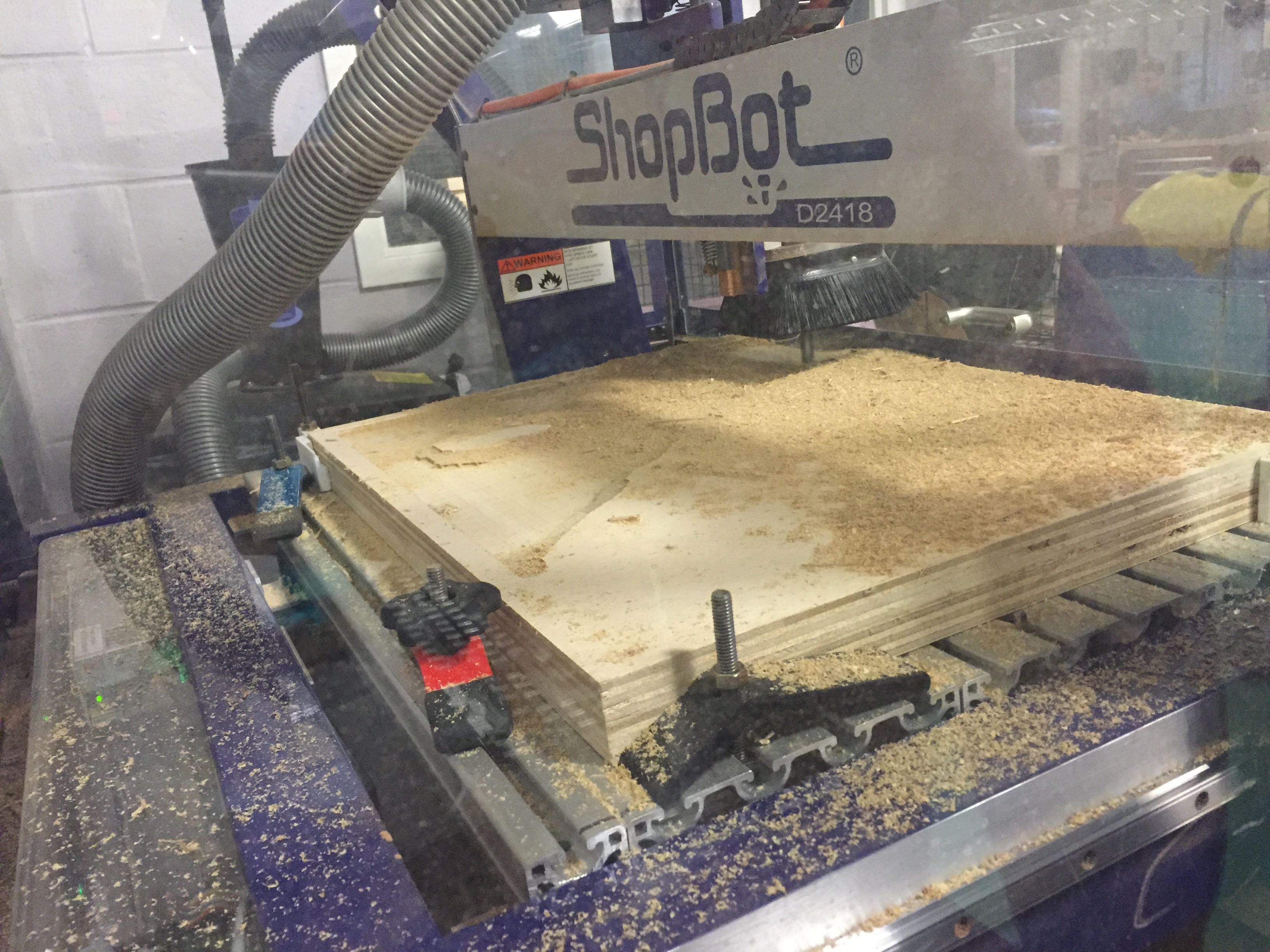
Once the wrap fit on the legs, I moved on to milling the model of Tufts. The pieces of plywood I was using were 22-1/2″ x 17-3/16″ x 1-1/2″, which is just about the size of the ShopBot bed (which is 24″ x 18″). This left very little room to put any clamps on, let alone enough clamps to make sure the piece wasn’t going to move while it was being milled. The few clamps I could get on were difficult to hold down as the knobs were too wide in diameter and kept hitting the sides of the stock piece. I decided to design a corner clamp (seen below) that would keep my piece square, straight in the X and Y directions, and have enough room to use the knobs without getting in the way of the material or the bit.
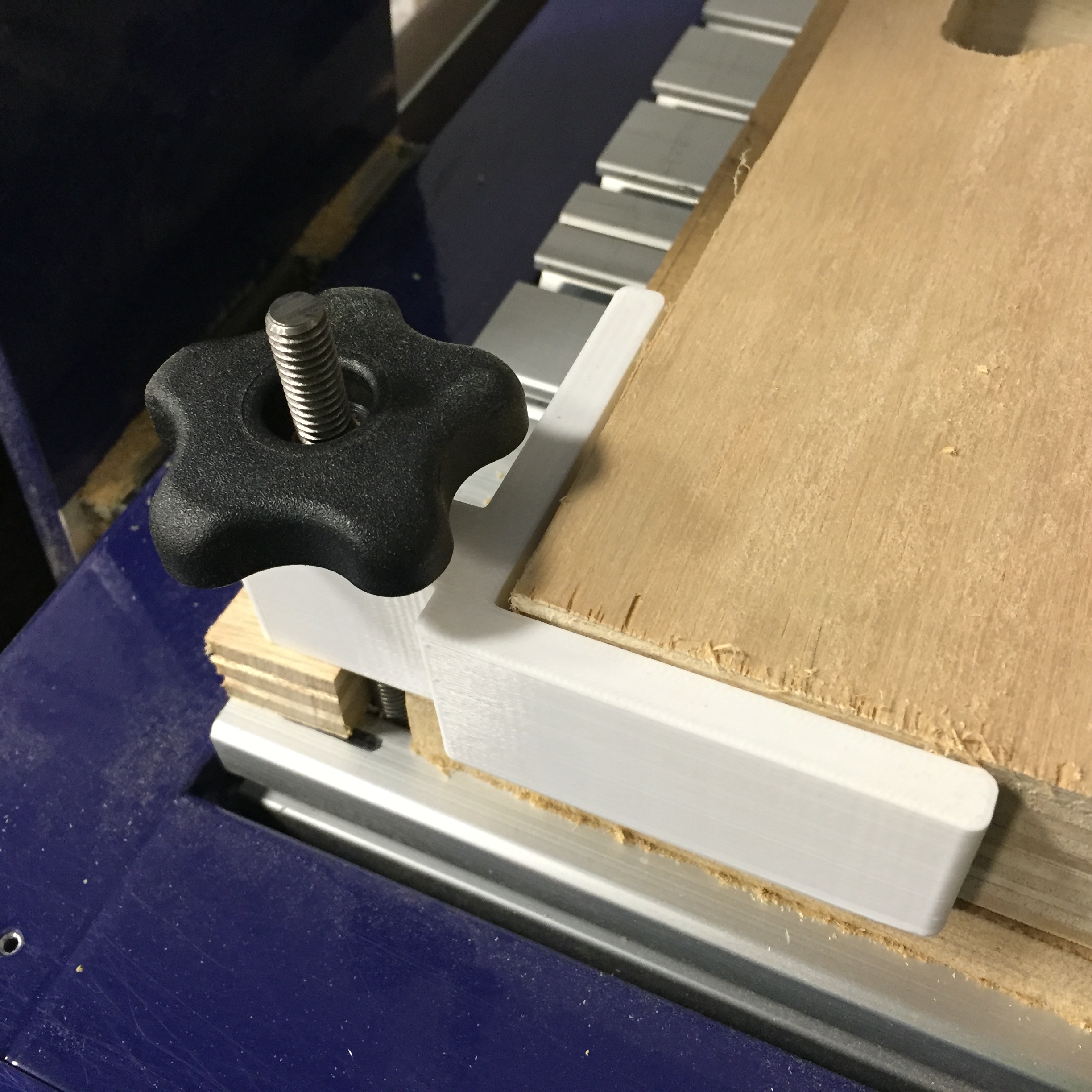
Corner clamp
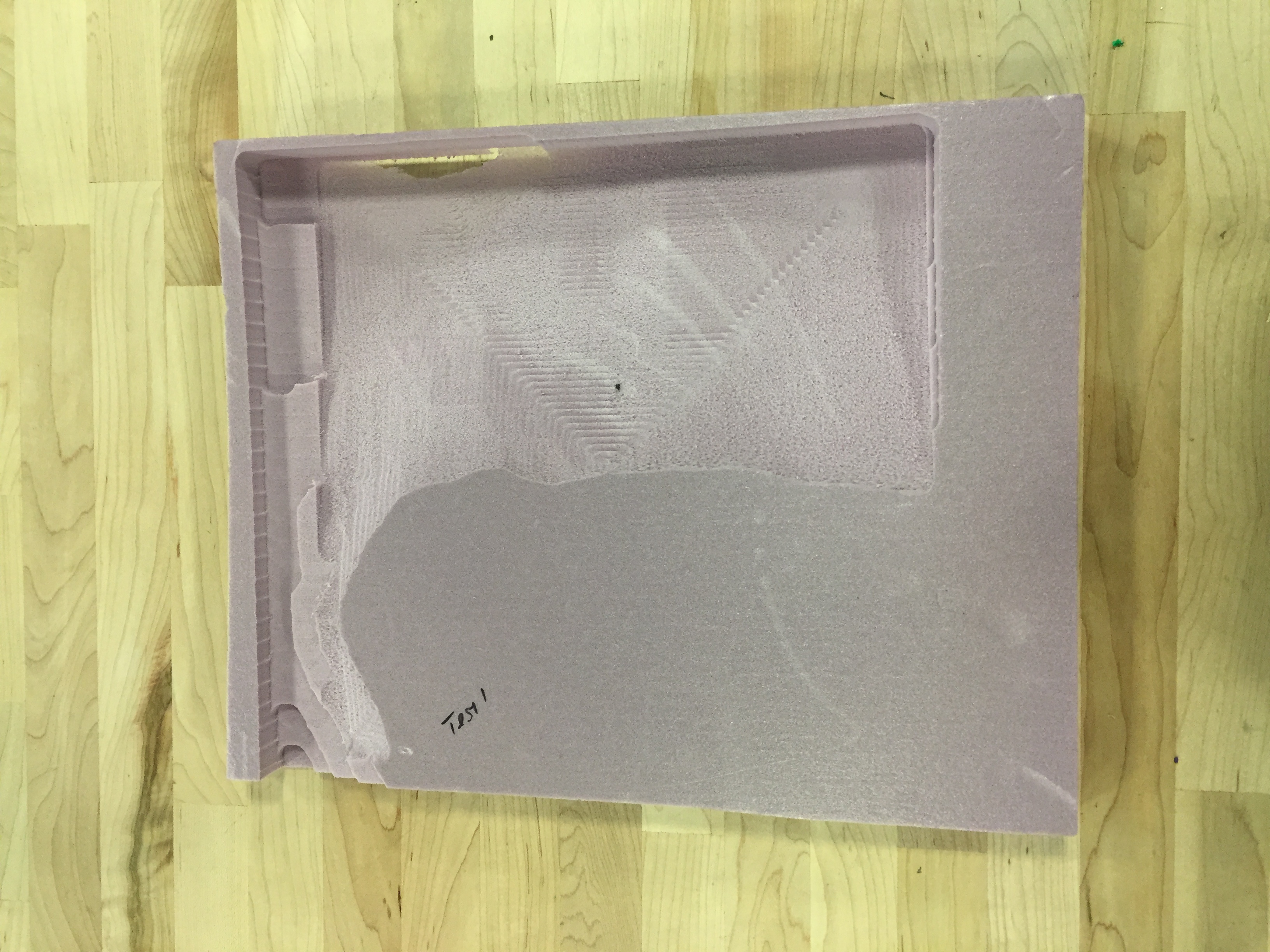
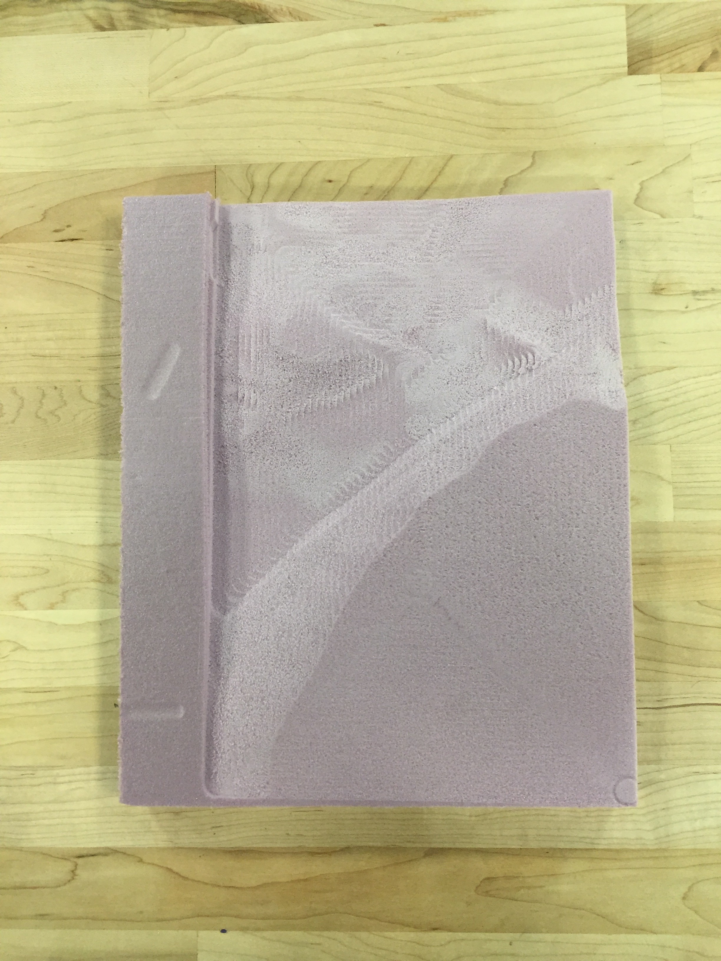
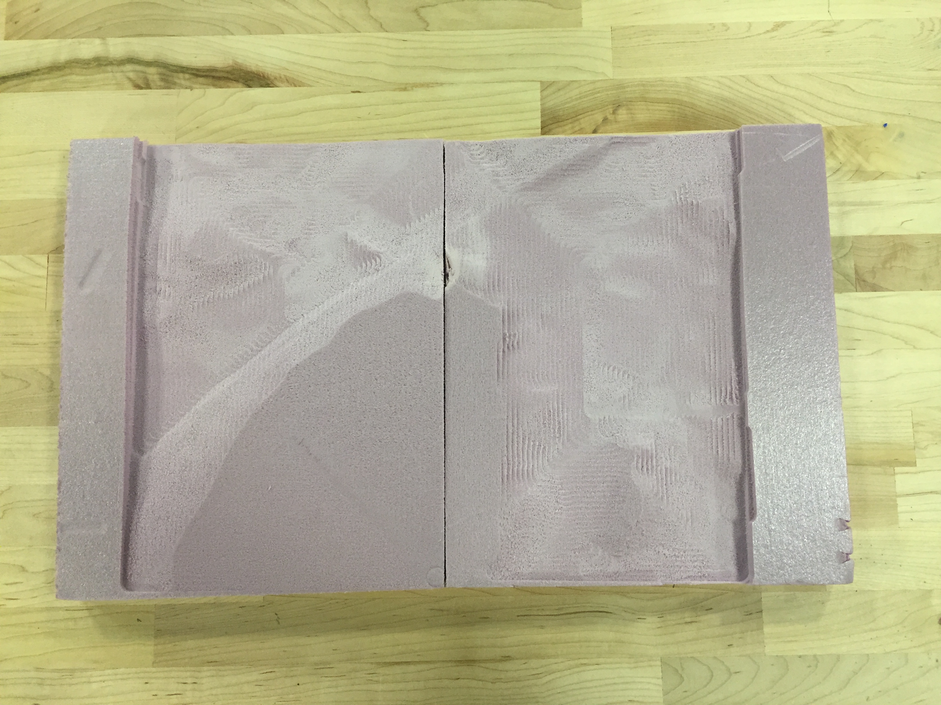
I 3D-printed the clamps so that in case they did get in the way of the bit, they wouldn’t damage the bit and could easily be re-printed. I did one final, to-scale model of the Tufts map in foam with the 1/” end mill bit before I used the plywood. The foam model turned out just as expected.
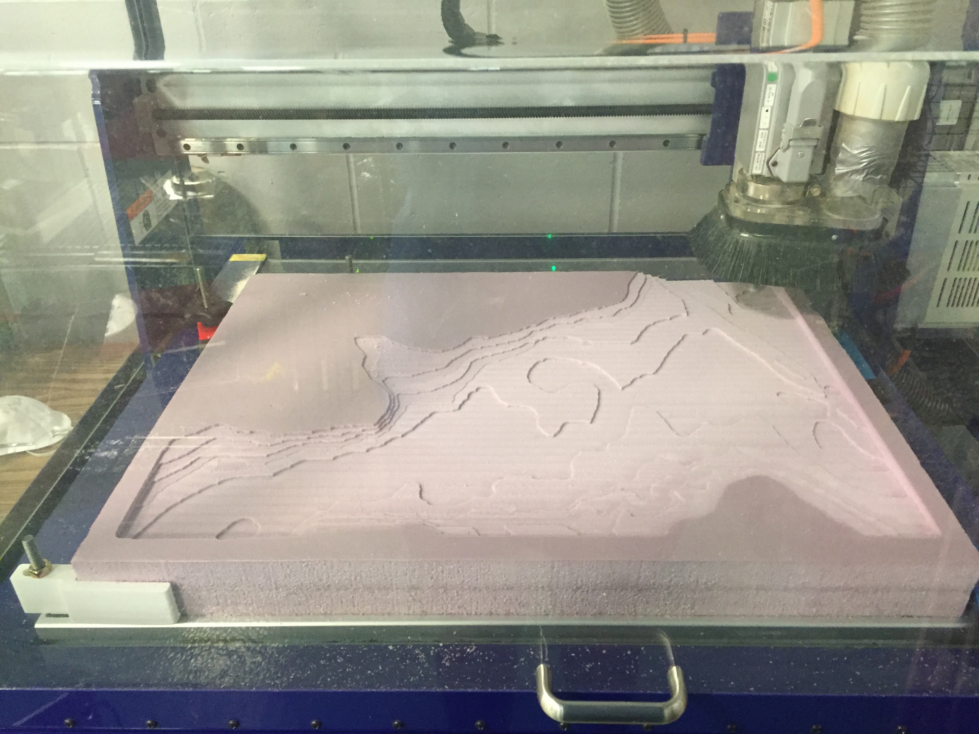
The practice foam being milled
I left the clamps in the same position, and just switched out the foam for the plywood, and ran the same program.
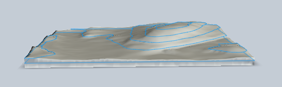
The plywood being milled for the final model
I repeated that process with the rest of the map sections to produce the base layer of the map.
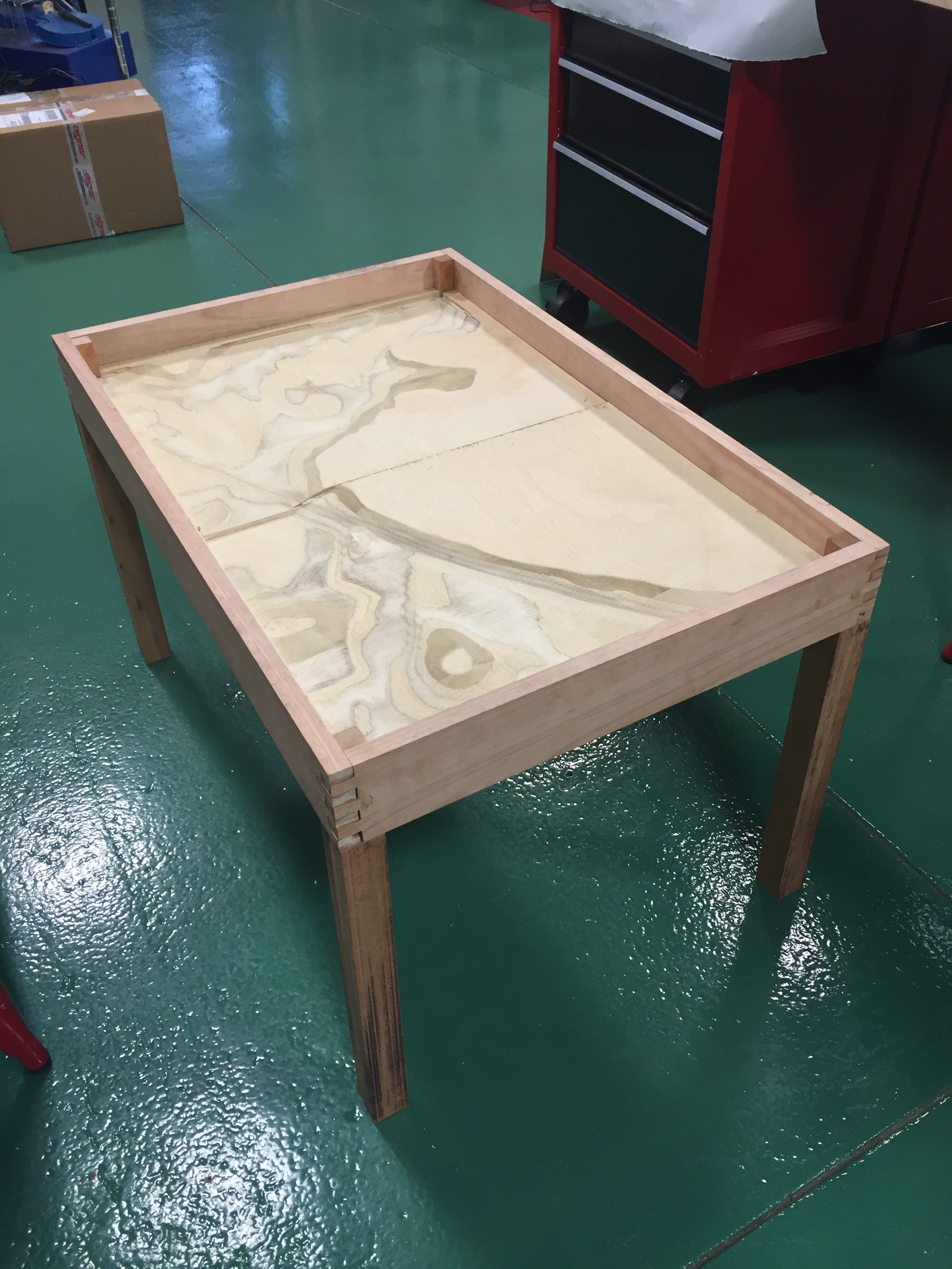
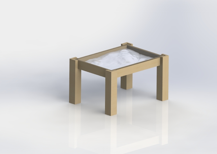
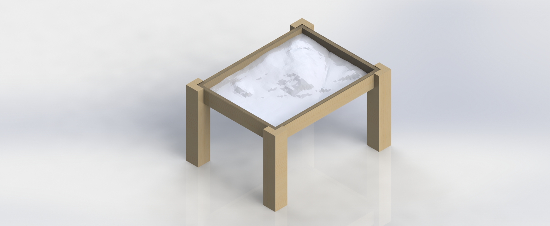
Coffee table with the base layer of the model in place
The two top layers are currently being milled and will be added to the table shortly. The rest of the table has been stained and is about ready to be moved to it’s final destination in the Design Lab!