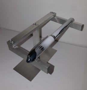
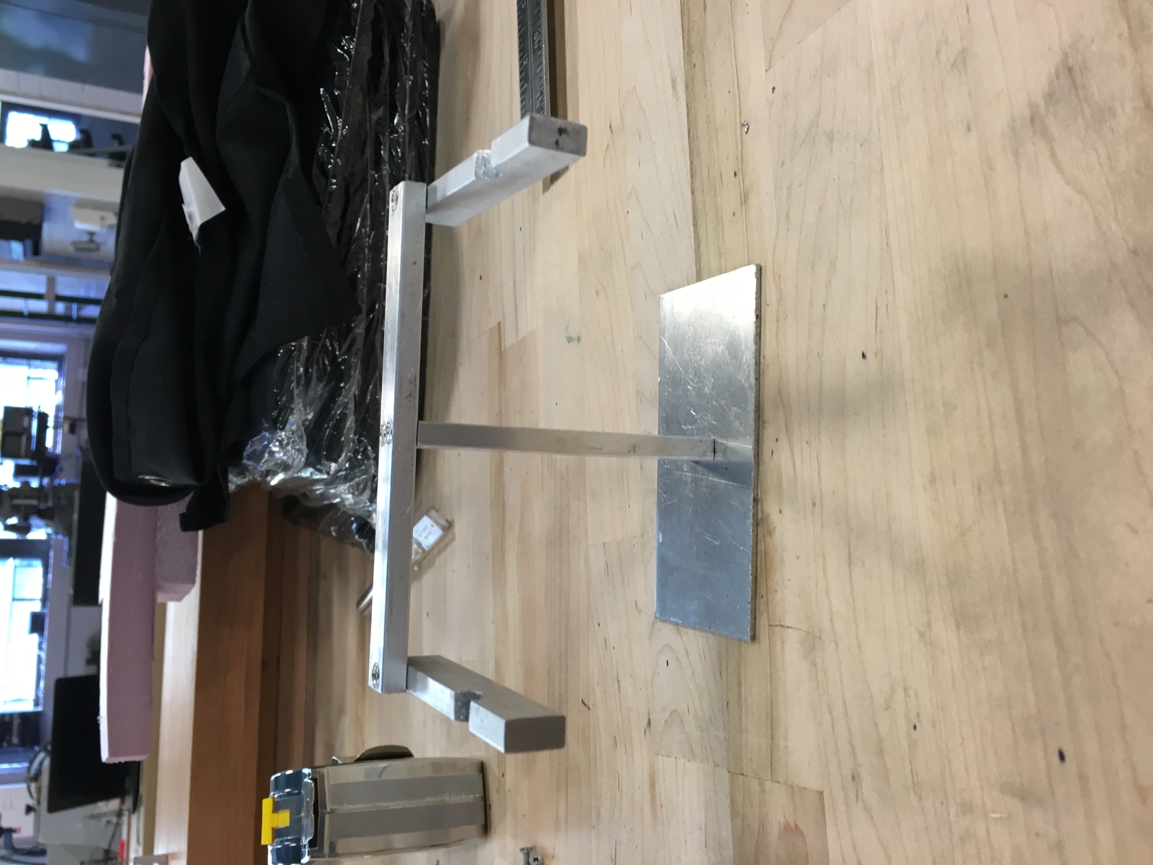
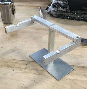
The final edition of the penholder has been completed and nearly approved for commission as one of the shop training projects. In this most likely final blog post, we would like to do a brief review of the purpose of the project as well as go over a further inspection of the penholder and discuss the final outcome.
Purpose
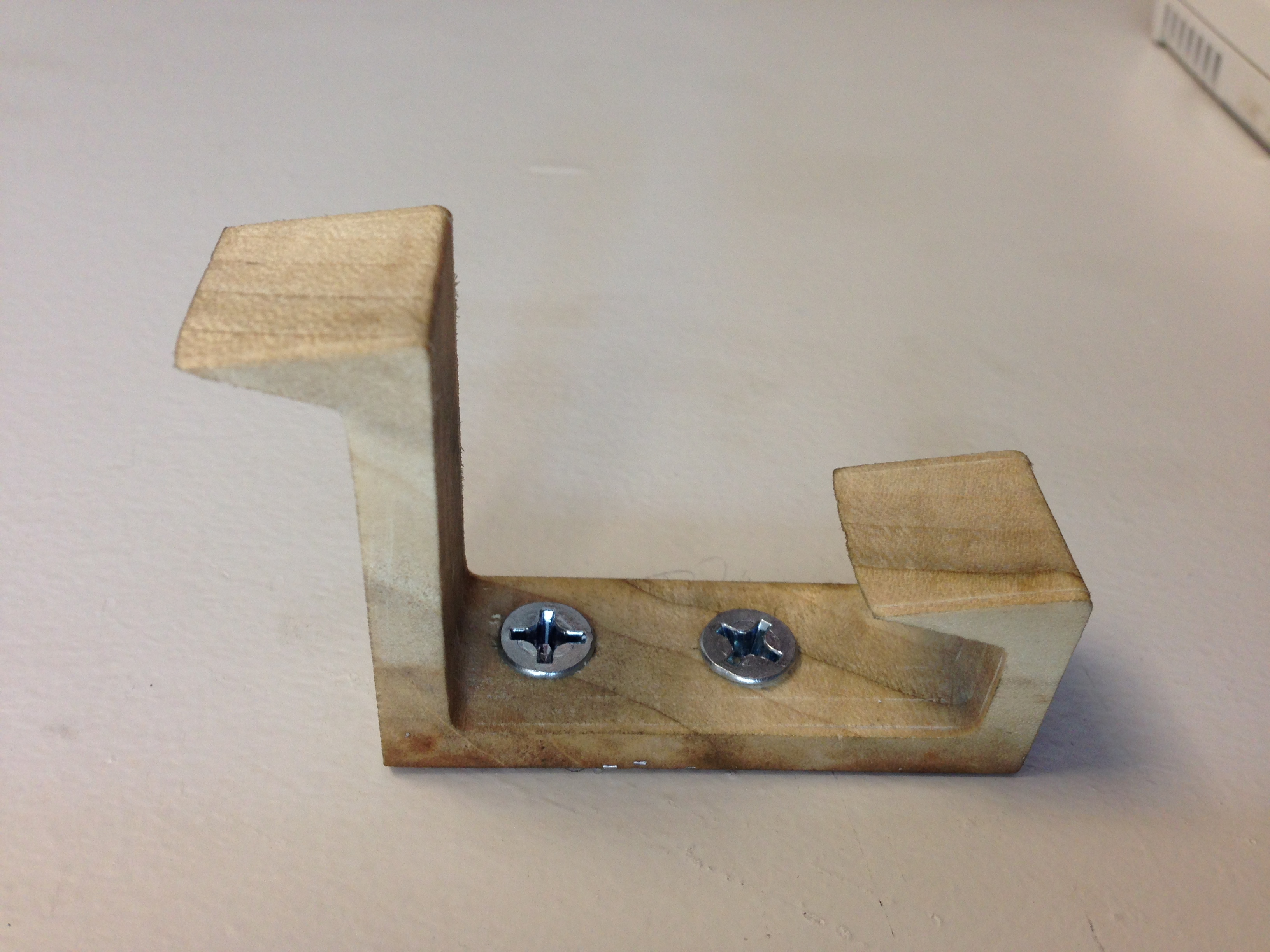
To review, the penholder project concept was birthed as a way to give students more options for fabricating a project that gives them appropriate training with the shop’s power tools. We figured that a project is the best way for students to be trained, but we realized that there were some complaints with the old project, which was a wall hook. The wall hook was impractical as it had to be drilled into a wall for usage. However, drilling in dorm walls goes against residential life policy at Tufts. In addition, the project was also relatively dull and it also existed as the only option available for power tool certification. Therefore, we brainstormed ideas for new project ideas that were practical, creative, but also didn’t sacrifice using all of the power tool equipment, override the budget, and take too much time. Thus, the penholder idea was born.
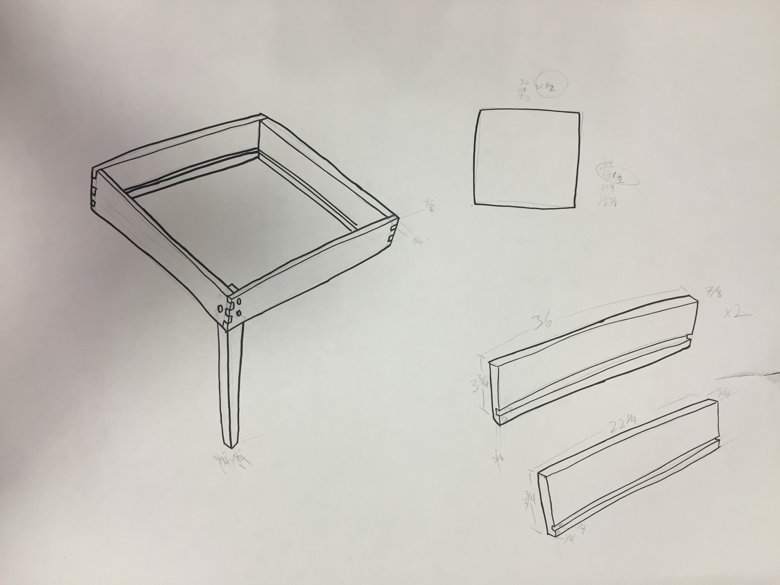
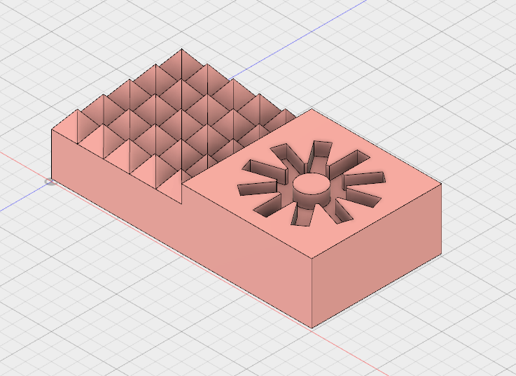
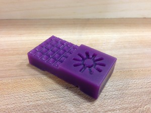
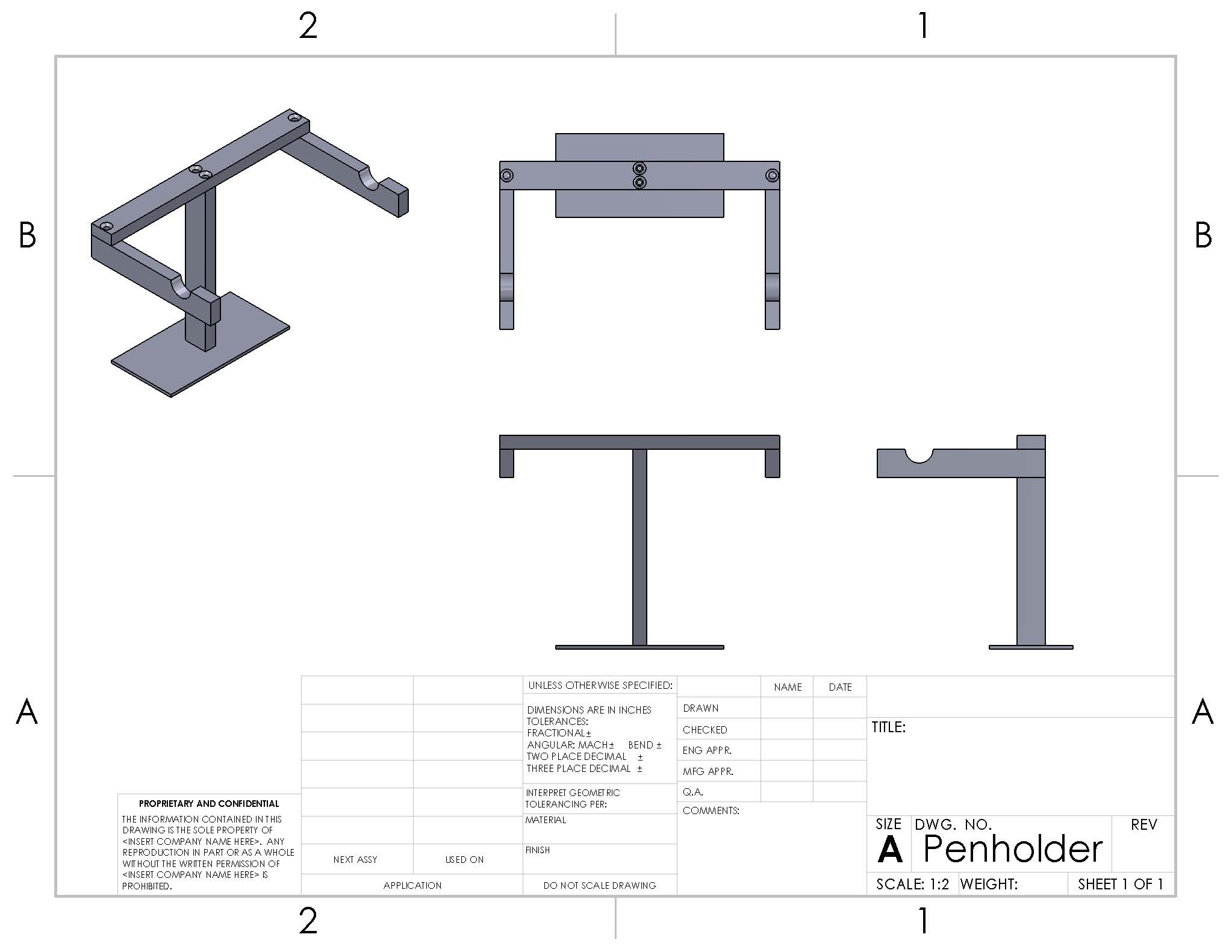
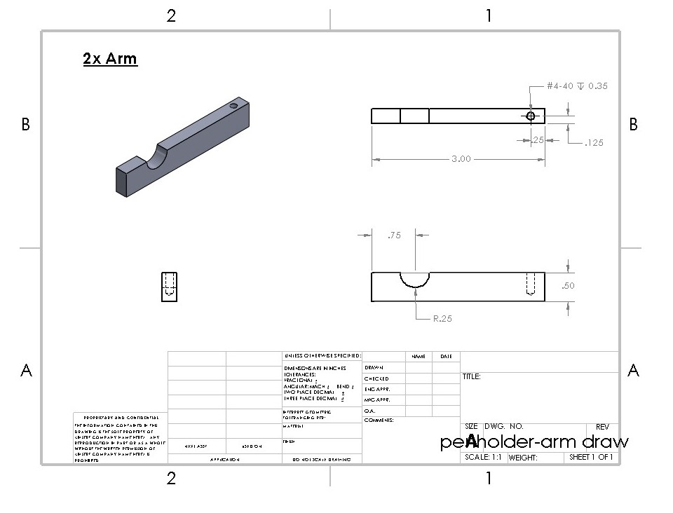
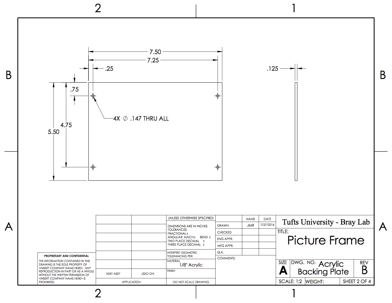
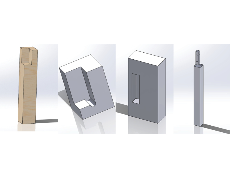
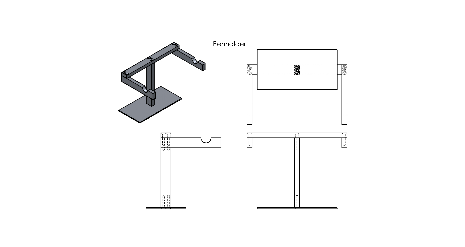
The final penholder CAD design is shown below:
Build Process
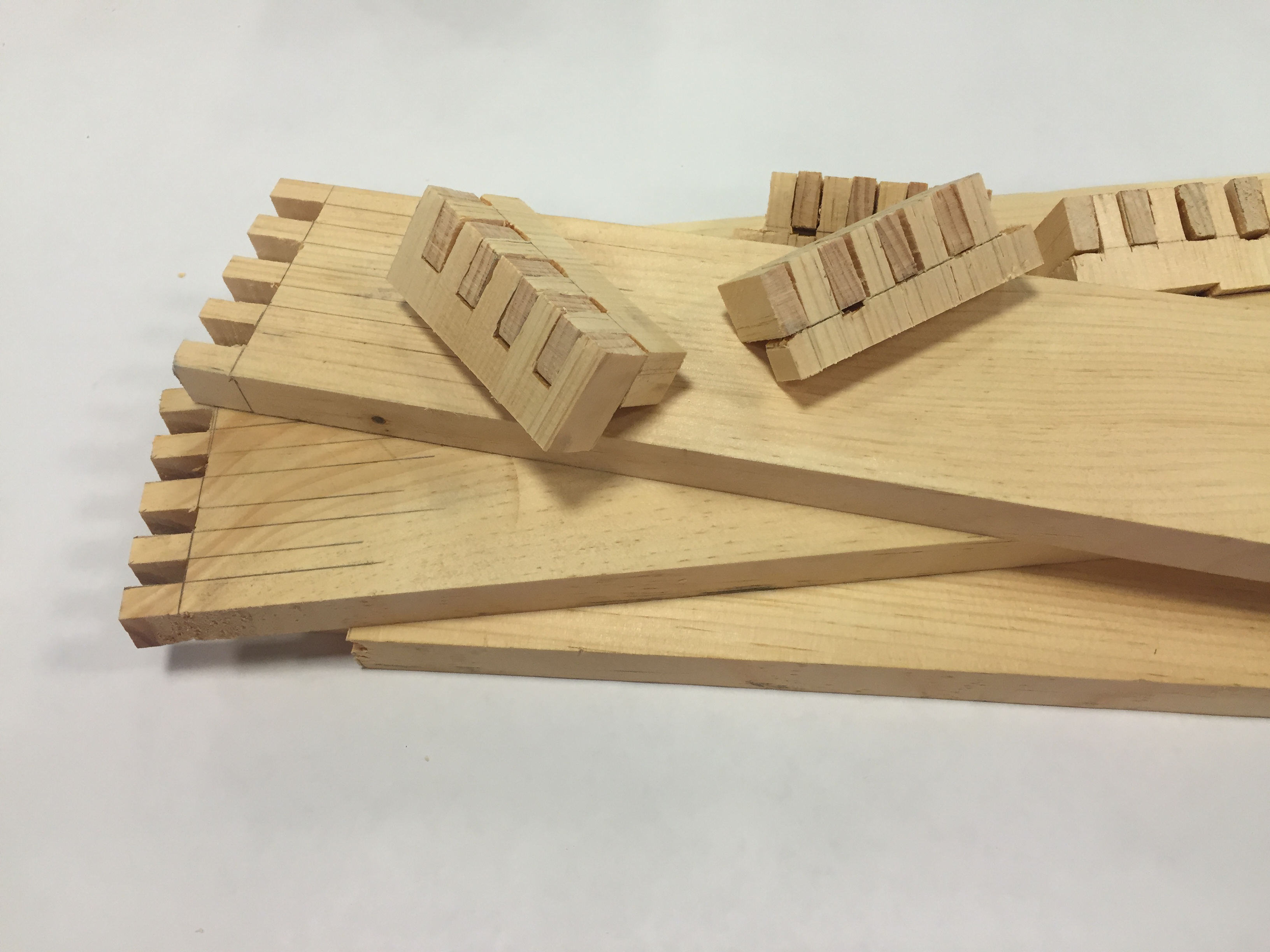
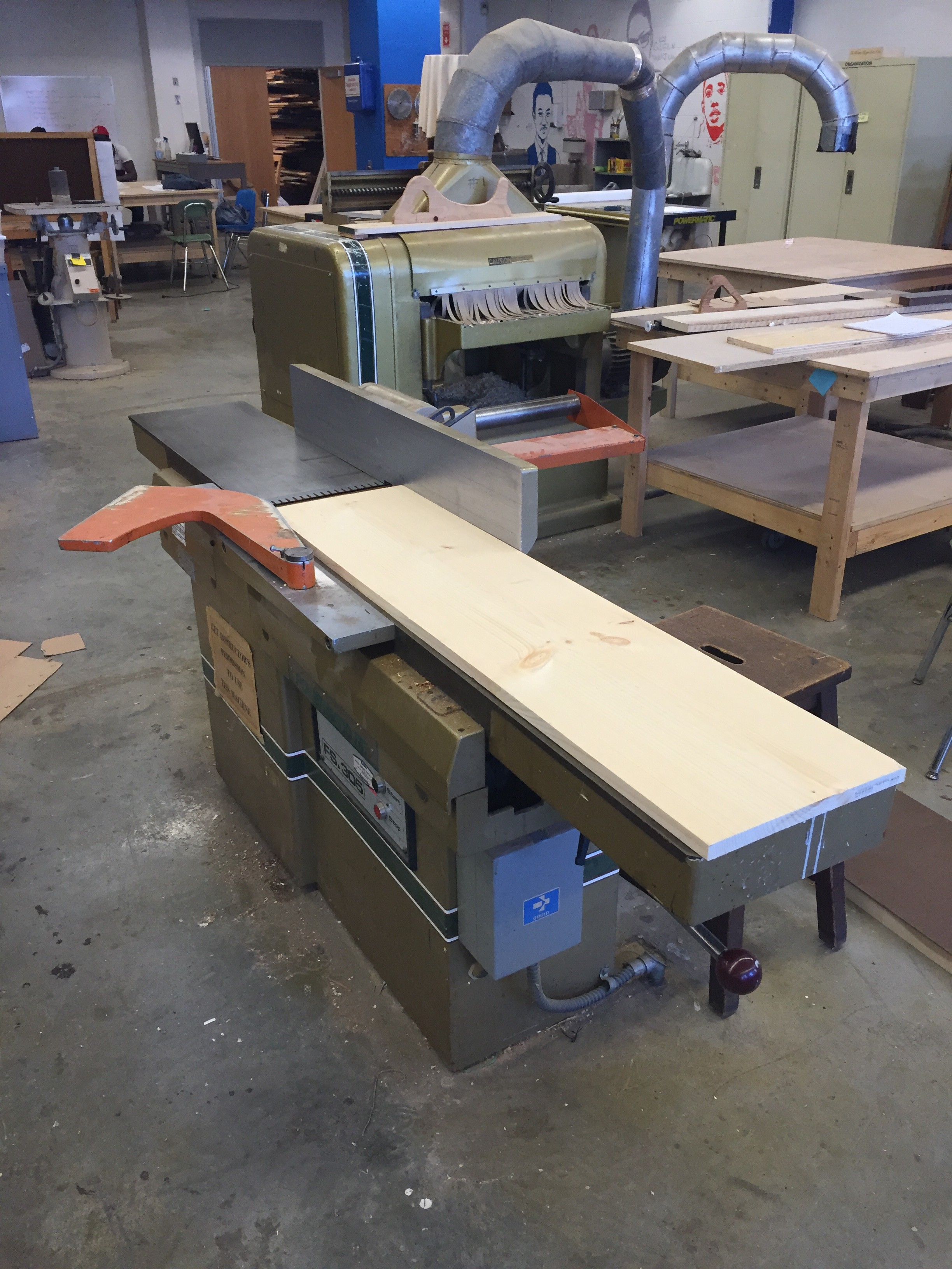
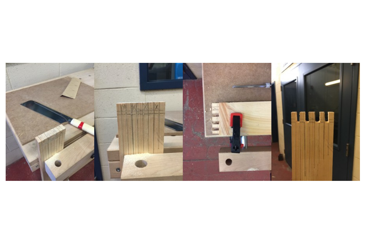
Naturally, it is important to describe the details of the fabrication process. The project incorporated the use of every power tool in the yellow zone of the shop. Therefore, we succeeded in our main objective – giving students adequate training in all tools. In terms of a time estimate, we didn’t keep a sturdy time count, but it was estimated the project would take about 4 hours to complete. It is also important to recognize time for errors and miscalculations, which are important as part of the learning process. Therefore, the project is a quite a bit long, but not too long to dismay students, we think.

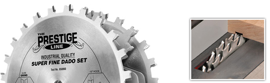
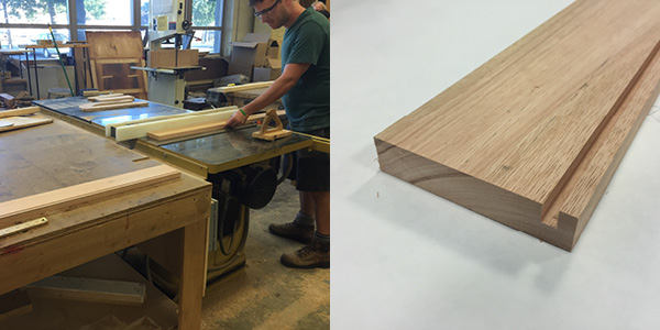
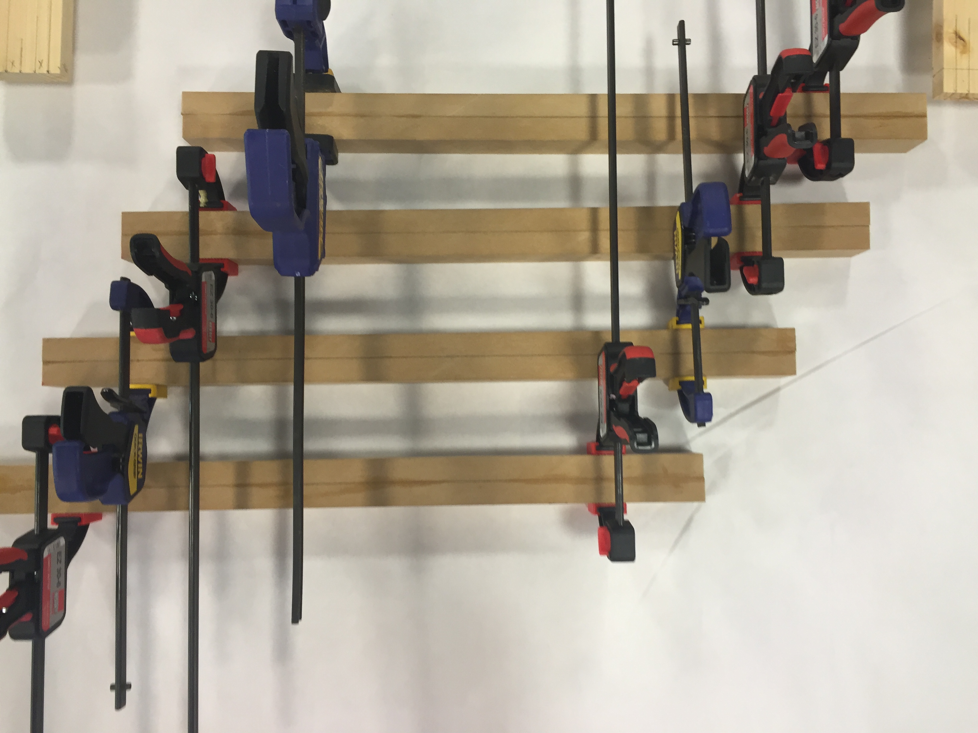
Tool Usage Diagram
Further inspection: hindrances and benefits
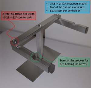
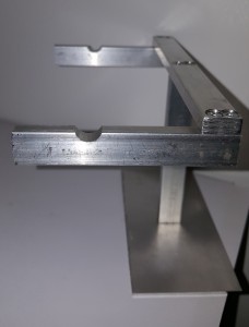
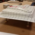
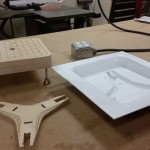
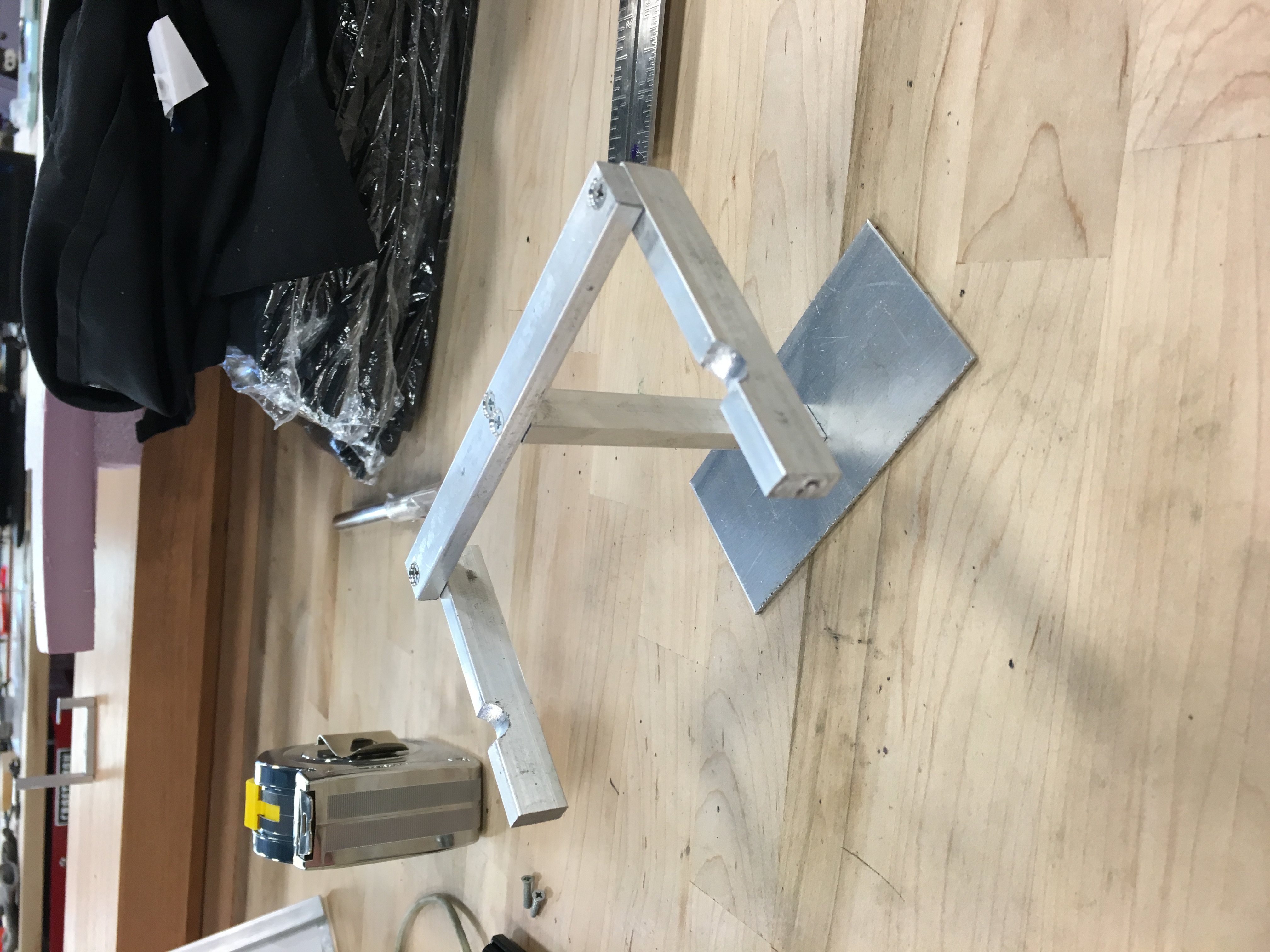
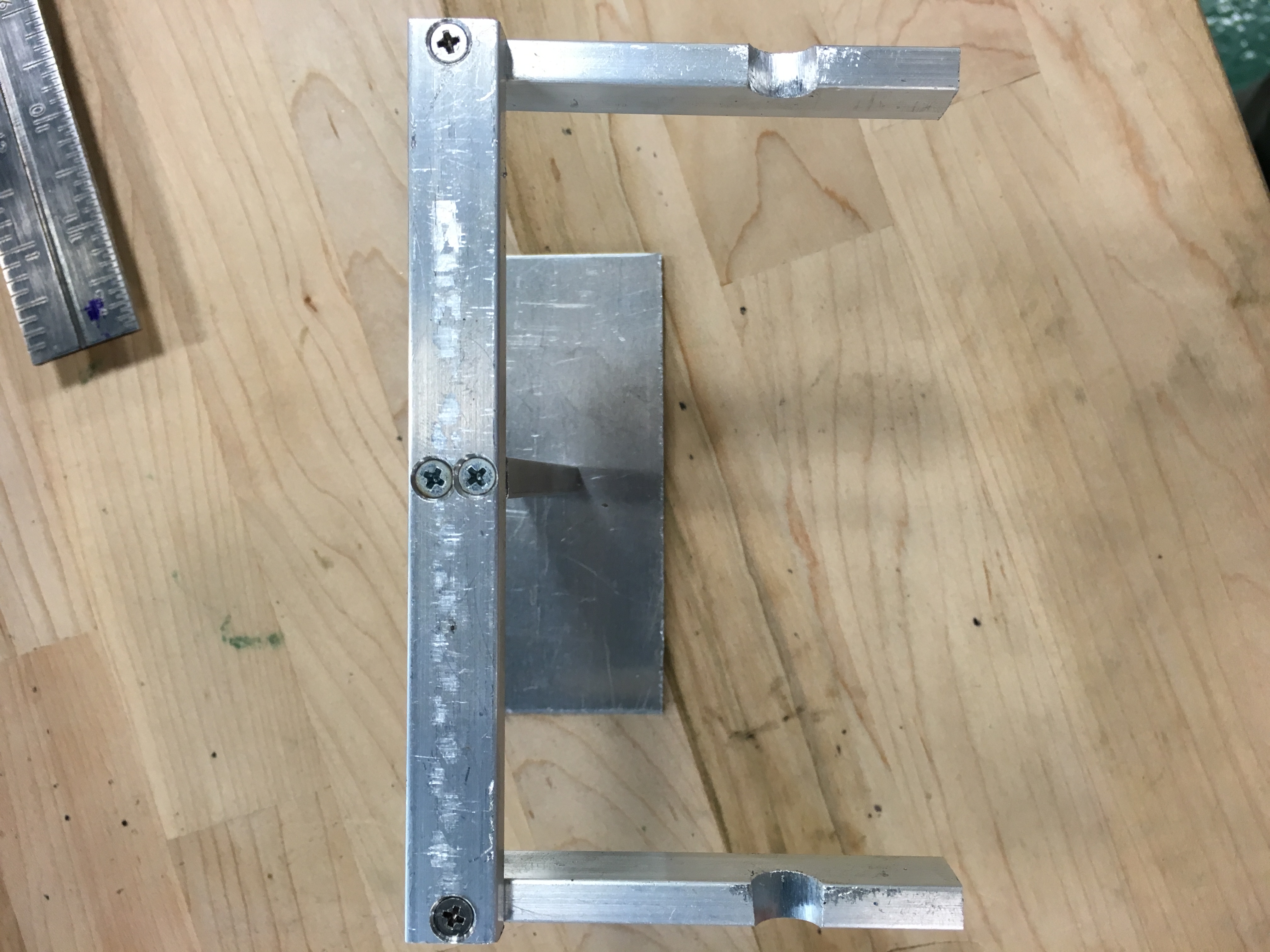
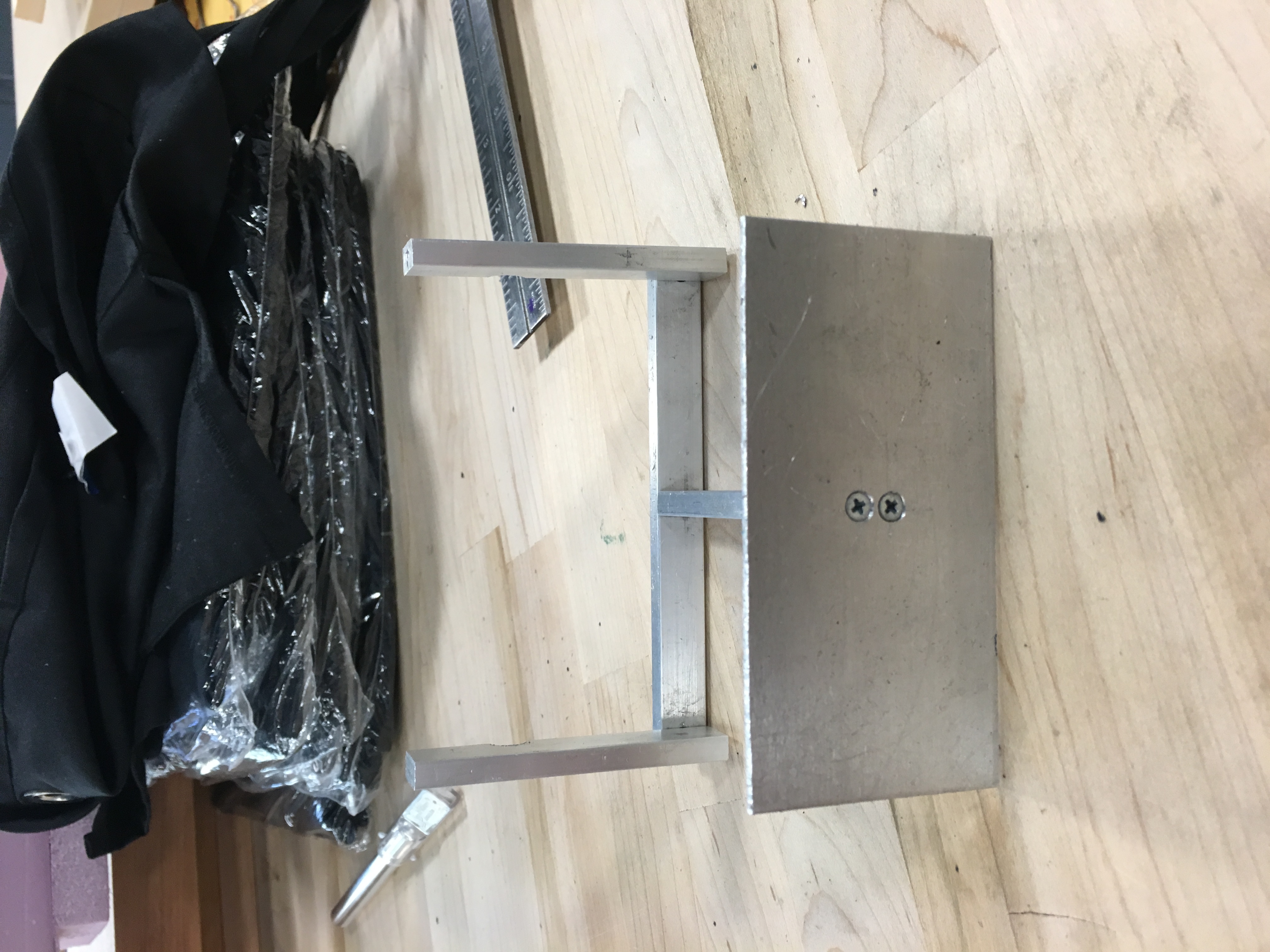
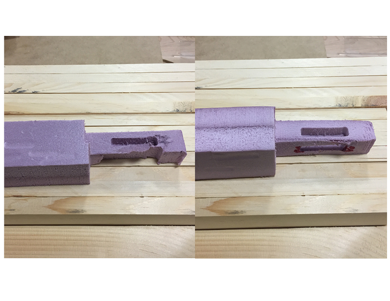
We certainly like the design and practicality of the penholder. However, one aspect that gave us some trouble was the number of holes needed for the design. If we had more time to develop a better design, we would try to brainstorm a way to reduce the number on the top support; an attempt is shown below but would not securely fasten the arms with only one hole. Hole reduction would save time needed to fabricate, as well as decreasing the chance of having to redo the most intricate piece. Additionally, the penholder used more material and cost about 2.8x the wall hook.
Previous penholder design
An appealing aspect of the penholder is that there is slightly more margin of tolerance than the wall hook. Since the wall hook worked with such small pieces, it was incredibly easy to make a small error, but small errors would also be overwhelmingly apparent. Since the penholder involves working with bigger pieces, errors can definitely still be noticed, but there is slightly more room for lesser mistakes without affecting its aesthetic or functionality; this is important because most people will be able to make a functional device. We noticed that many people would complete the wall hook and they would look quite crooked and in some cases, unusable. We hope that people will still make mistakes so they can learn, but also be happy with their object at the end of fabrication.
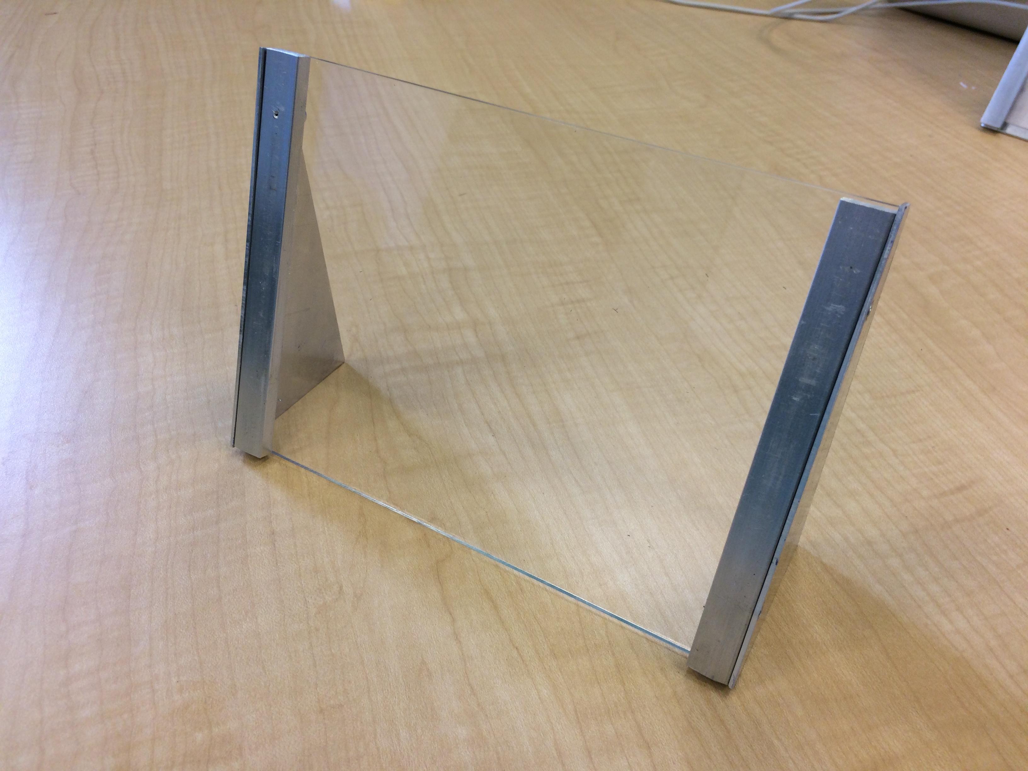
Additionally, it may be worth mentioning that we polled some incoming freshmen about which design they prefer if they had to fabricate a project. We showed them the completed penholder and wall hook and the majority preferred the penholder. Since this was such a small sample size, it doesn’t capture the entire sentiment and tendencies of the student body’s preferences, but we just thought it their preference was reassuring. Also, it is important to understand that the wall hook will still remain a viable project for students to create for their training. They will now just have the option to do either the wall hook, penholder, or picture frame (which will be discussed in a separate blog post).
We have submitted our drawings for final review by the fabrication supervisor. We are excited that the design will hopefully be approved and ready for fabrication by students in the upcoming semester.
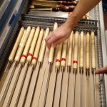
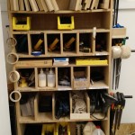
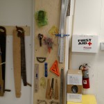
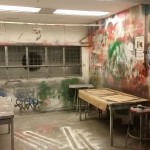
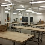
Other Media
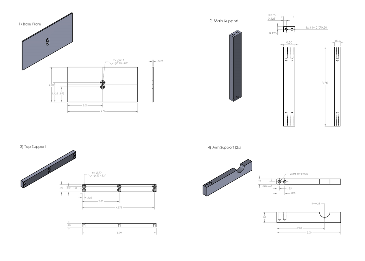
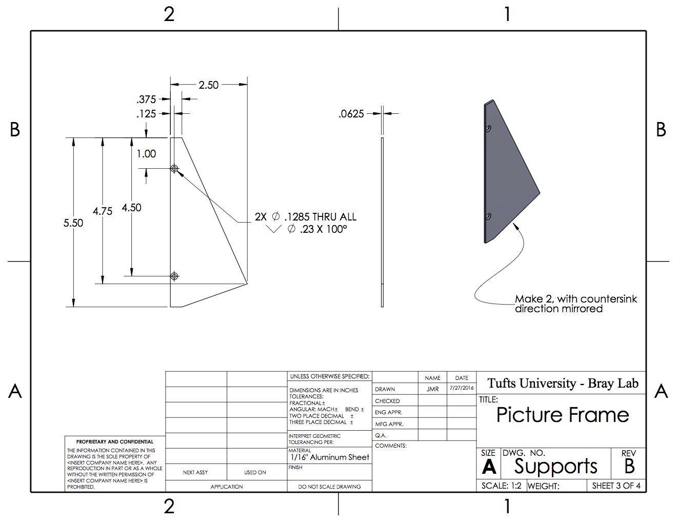
Part Specifications